How are electric motors made? For the cast-iron IEC three-phase induction motors used on industrial pumps, fans and conveyors, the answer is a sequence of foundry, stamping, winding and assembly steps, followed by routine electrical and mechanical tests. This article walks through that process for a typical squirrel-cage, totally enclosed fan-cooled (TEFC) machine. It is not a DIY build guide, and it is not about hairpin or permanent-magnet traction motors used in electric vehicles.
Knowing the steps helps when you read a quotation or a routine test report: you can see which parts of the machine were cast, stacked, wound, impregnated, balanced and then checked before painting and packing.
1. Casting and Machining the Frame and End Shields
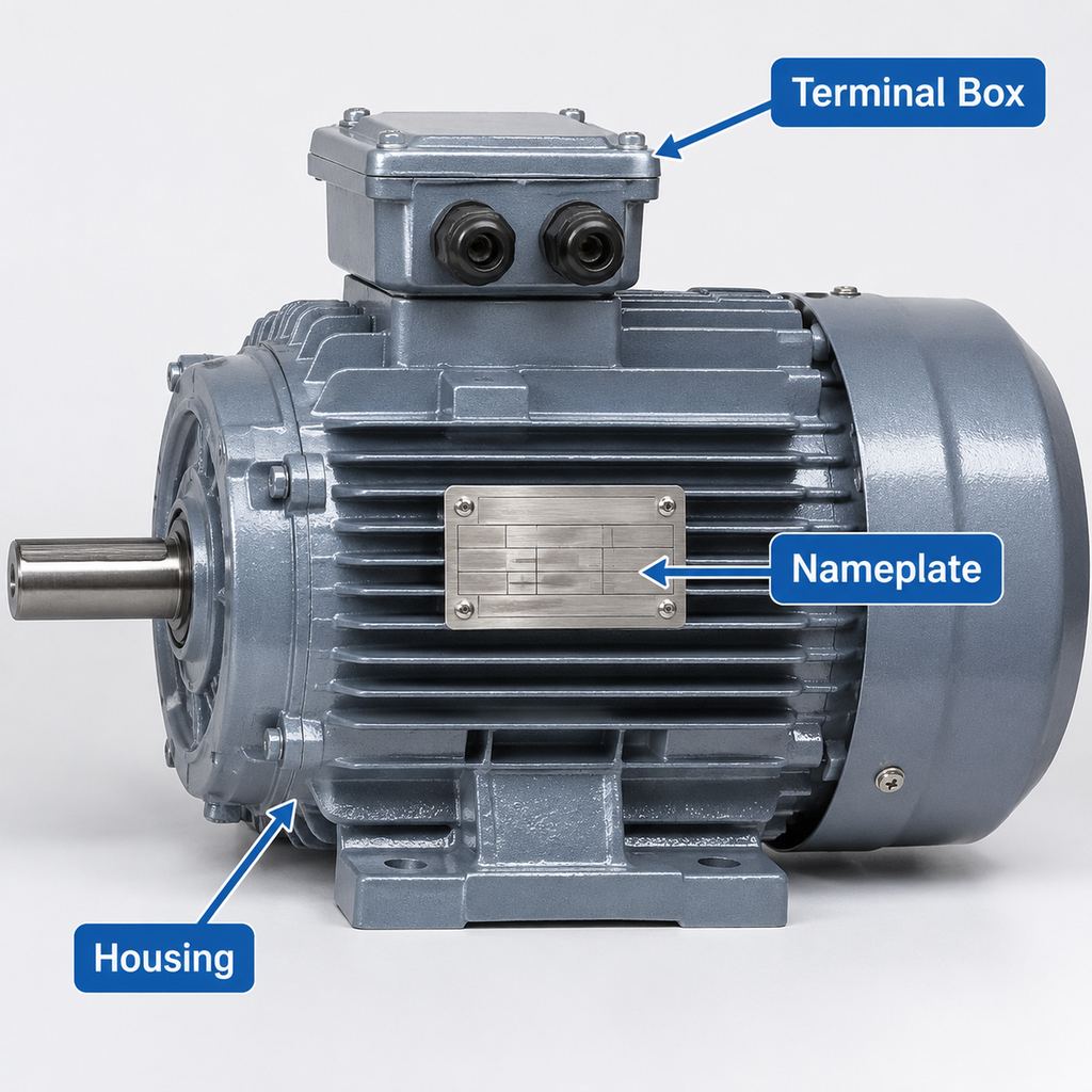
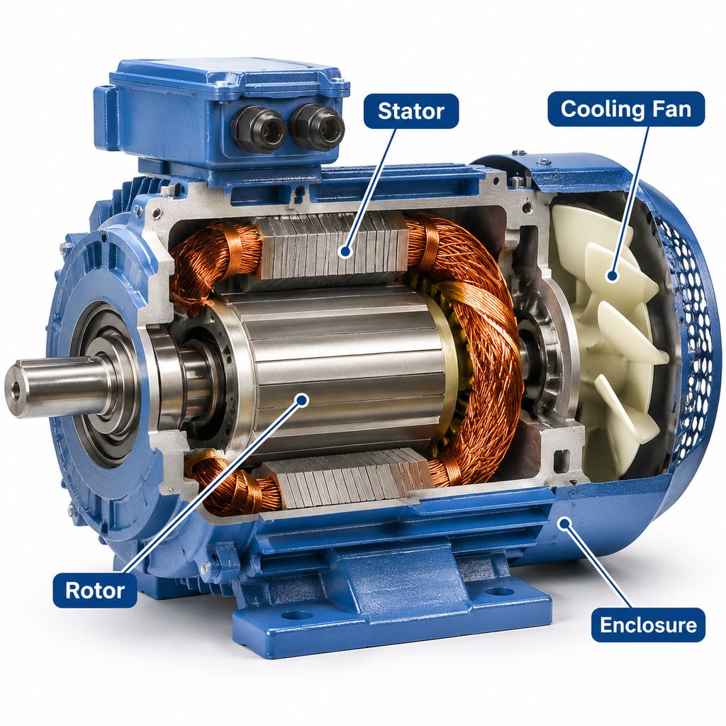
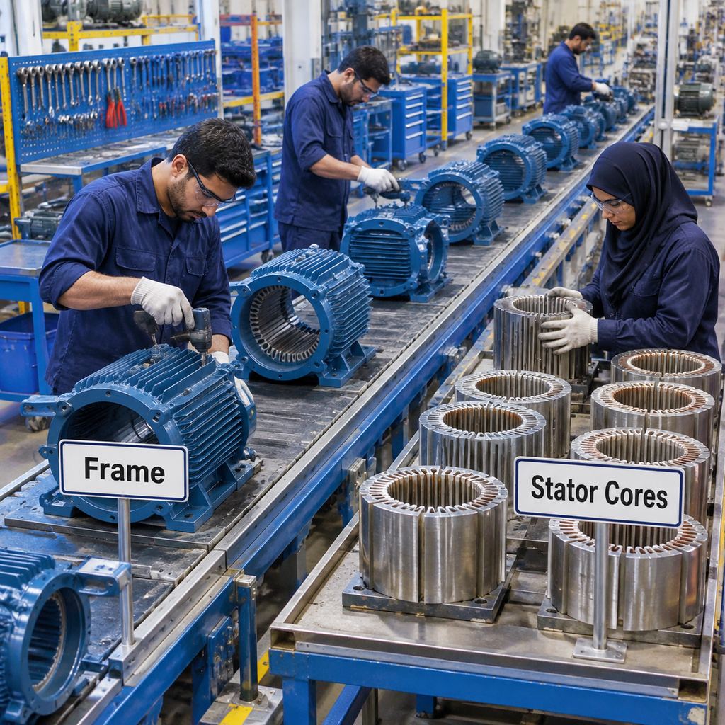
The frame is the structural housing. For many industrial IEC motors it is cast iron, chosen for rigidity and vibration damping on heavier pumps, crushers and similar duties. JWMotor’s Y2 pages specify HT200 cast iron for the frame and end shields; other series are also described as cast-iron machines for demanding rooms. This article does not assign a grade to every IEC motor on the market.
After casting, the frame and end shields are machined so that bearing bores, spigots, feet or flange faces, and the land that will hold the stator core are concentric and to drawing. Errors at this stage show up later as vibration, rubbing, or an uneven air gap.
2. Stamping and Stacking the Laminations
The stator and rotor cores are not solid steel. They are stacks of thin electrical-steel laminations, stamped and then stacked and locked or welded into a core. Thin, insulated sheets interrupt eddy-current paths and lower iron loss compared with a solid core. Grade and thickness are a design choice for the efficiency class and supply frequency; take them from the manufacturer’s material specification rather than assuming a number. JWMotor describes its standard core steel on its silicon-steel page.
The stator stack has slots on the inner diameter for the windings. The rotor stack has slots on the outer diameter for the cage bars.
3. Winding and Inserting the Coils
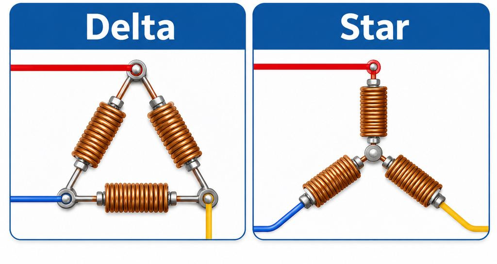
Enameled winding wire—typically copper on industrial IEC stators—is formed into coils and inserted into the stator slots. Slot liners insulate the copper from the core. Phase insulation separates different phases in the winding overhangs so that a turn-to-turn or phase-to-phase short is less likely. The coil leads are brought out ready for the terminal box.
How those windings are arranged, and what a rewind involves, is covered in what is a motor winding; this page does not repeat that article.
4. Varnish Impregnation and Baking
Once the coils are in place, the stator is impregnated with insulating varnish and then baked to cure it. Two common factory methods are dip-and-bake and vacuum pressure impregnation (VPI). VPI uses vacuum and pressure to drive varnish into the slot and the winding head, which helps fill voids. JWMotor’s insulation-class page states VPI and a Class F insulation system as standard.
The cured varnish binds the windings mechanically, improves dielectric strength, and helps conduct heat out of the slot. Cycle times, bath temperatures and vacuum levels vary by process. If you need those figures, ask the manufacturer; they are not invented here.
5. Die-Casting the Rotor Cage, Shaft Pressing and Balancing
For a squirrel-cage rotor, molten aluminum is die-cast into the rotor slots so the bars and end rings form one cage. A steel shaft is then pressed or otherwise fitted into the rotor core. The completed rotor is dynamically balanced so residual unbalance does not appear as vibration at the bearings once the motor is running.
The rotor has to remain a single assembly: laminations tight on the shaft, cage intact, and any balance correction applied the way the factory records it. A wound-rotor (slip-ring) machine is a different construction and is not the subject of this process.
6. Bearing Fitting, Terminal Box and Fan
Bearings are fitted to the shaft and into the end-shield bores, and the rotor is inserted through the stator bore with the designed air gap. The end shields are bolted to the frame. The terminal box is mounted and the winding leads are landed on the terminal board.
A cooling fan is fitted at the non-drive end, inside the fan cover. On a standard single-shaft motor the shaft extends only at the drive end. A second shaft extension at the non-drive end, when needed for a brake or encoder, is a customization, not the default layout.
7. Routine Factory Tests, Painting and Packing
Before paint and packing, the assembled motor goes through routine factory tests. Typical items are:
- Winding resistance, including a check that the phases are reasonably balanced
- Insulation resistance between windings and earth
- Hi-pot (dielectric withstand) between windings and earth
- A no-load run, to look at current, balance and direction of rotation
- Vibration and noise
A finish coat and packing follow a pass. When a test report is supplied, it should name the tests that were done and the results. This article does not invent pass/fail values or test voltages. How insulation resistance is measured in the field is explained in how to meg a 3-phase motor; a broader bench procedure is in how to test a 3-phase motor. Those procedures are not repeated here.
| Step | What is made or checked | Why it matters |
|---|---|---|
| Cast and machine the frame and end shields | Cast-iron housing, bearing bores, mounting faces | Alignment, stiffness and a true air gap |
| Stamp and stack laminations | Stator and rotor cores in electrical steel | Limits eddy-current loss in the magnetic circuit |
| Wind and insulate | Coils, slot liners, phase insulation, leads | Produces the rotating field and sets dielectric strength |
| Impregnate and bake | VPI or dip varnish, then curing | Binds windings, fills voids, helps heat flow |
| Cast the cage, fit the shaft, balance | Aluminum squirrel cage on the shaft | Torque production and low vibration |
| Assemble bearings, terminal box and fan | Complete TEFC machine, fan at the non-drive end | Ready for electrical and mechanical tests |
| Routine tests, then paint and pack | Resistance, IR, hi-pot, no-load, vibration and noise | A record you can ask for with the order |
What Buyers Should Check
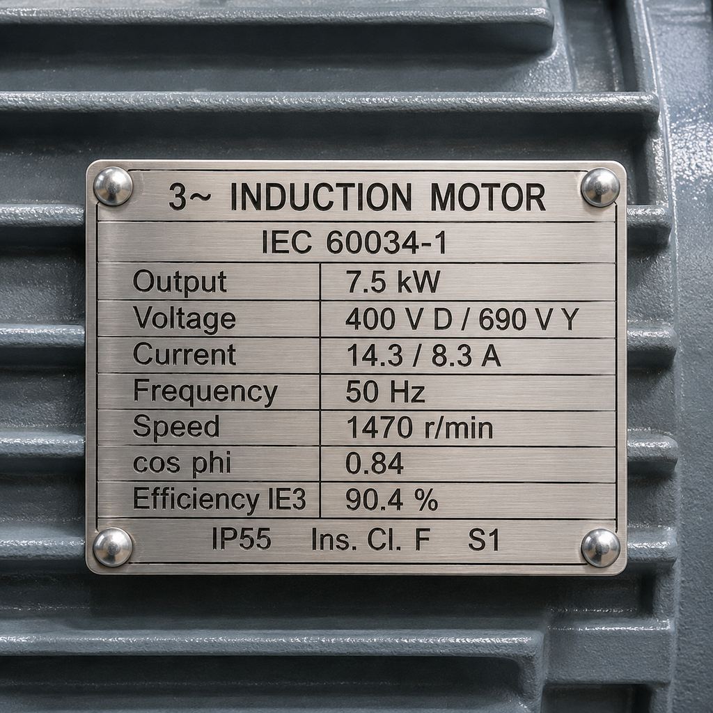
When you source a cast-iron IEC motor, ask for more than a nameplate photograph.
Routine test reports. Request the routine test record for the unit or type—winding resistance, insulation resistance, hi-pot, no-load, and vibration or noise as applicable. A report that only restates the nameplate is not the same as a test record.
IE efficiency class. IE2, IE3 or IE4 is a rated efficiency class, not a marketing label. It describes the permitted losses at the rated point and therefore the energy the motor will use over its life. How efficiency is defined and checked in the field is covered in how to determine motor efficiency.
Insulation class. Many industrial IEC motors, and JWMotor’s stated standard, use Class F insulation. Confirm the class on the nameplate and in the quotation, together with the temperature-rise class if it is given.
IP rating. TEFC IEC motors are commonly IP55. Wet, dusty or washdown rooms may need a higher rating or different sealing, which is a customization point rather than something to assume from the catalogue photo.
When customization makes sense. It is worth asking for a non-catalogue build when the voltage or frequency is non-standard, the shaft must change (including a double shaft), the mounting is not the usual B3, B5 or B35 arrangement, the enclosure must go beyond the standard IP rating, or the winding needs thermal sensors such as PTC thermistors, PT100s or a bimetal switch. Those options are listed on JWMotor’s customization page. For a broader selection checklist, see how to choose a motor.
FAQ
How are electric motors made?
A typical cast-iron IEC three-phase induction motor is made by casting and machining the frame and end shields, stamping and stacking the stator and rotor laminations, inserting and insulating the stator coils, impregnating and baking the winding, die-casting the aluminum rotor cage, fitting the shaft and balancing the rotor, then assembling the bearings, terminal box and fan and running routine factory tests before painting and packing.
How are motors made if a higher efficiency class is required?
The same process steps apply. The difference is in design and materials—lamination grade and thickness, winding design, and the losses the finished motor is rated to meet—not in a separate “IE3 factory line.” Confirm the IE class on the nameplate and, where needed, with a test report.
What factory tests should a buyer expect?
At minimum, ask what routine tests were performed: winding resistance, insulation resistance, hi-pot, no-load, and vibration or noise. Field IR testing and a general bench procedure are described in the megger and motor-testing articles linked above.
When should a motor be customized instead of taken from the catalogue?
When the supply, shaft, mounting, IP rating or thermal protection does not match a standard frame. Start from a catalogue series and describe the exceptions, rather than rewriting the whole machine.
Standard Series and Custom Builds
JWMotor manufactures cast-iron IEC three-phase induction motors, including the Y2 (IE2), YE3 (IE3) and YE4 (IE4) ranges, listed under general-purpose motors. If the application fits a standard frame, those series are the usual starting point. If the shaft, voltage, mounting or protection has to leave the catalogue, use the customization page or browse all products. Inspection steps and material notes are also summarized on the quality and raw-material pages.