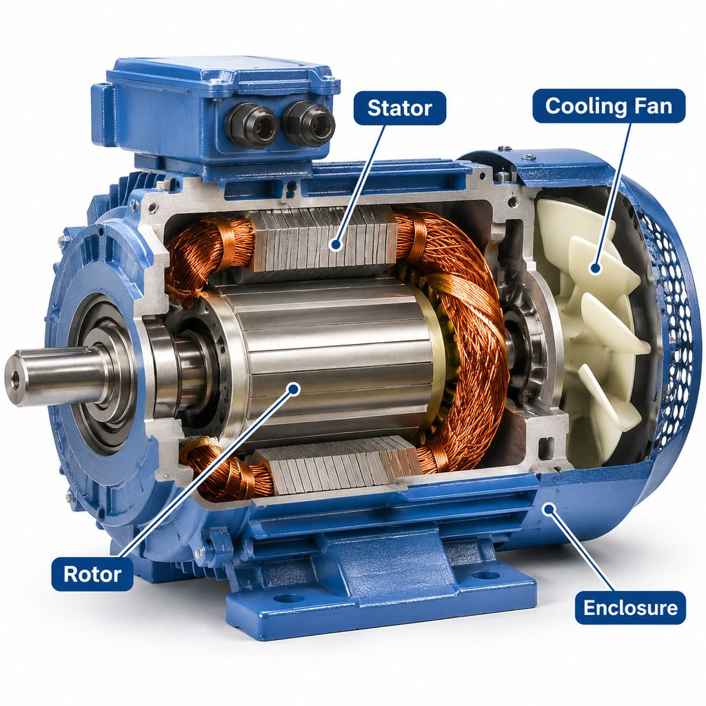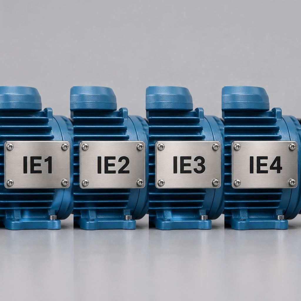
Understanding Full Load Current in 3-Phase Motors
Full load current (FLC) refers to the amount of electrical current a motor draws when it delivers its rated output power at rated voltage and frequency. Understanding FLC is crucial for engineers and buyers selecting, installing, or maintaining 3-phase motors, as it directly impacts the design and safety of electrical systems. A correct FLC value ensures that power supply equipment, such as cables, circuit breakers, and overload protection, is appropriately sized to handle the motor’s electrical load without risks of overheating, excessive voltage drop, or nuisance tripping. For tasks ranging from selecting the right motor to checking whether a datasheet is consistent, grasping FLC principles is essential for reliable and efficient motor operation.
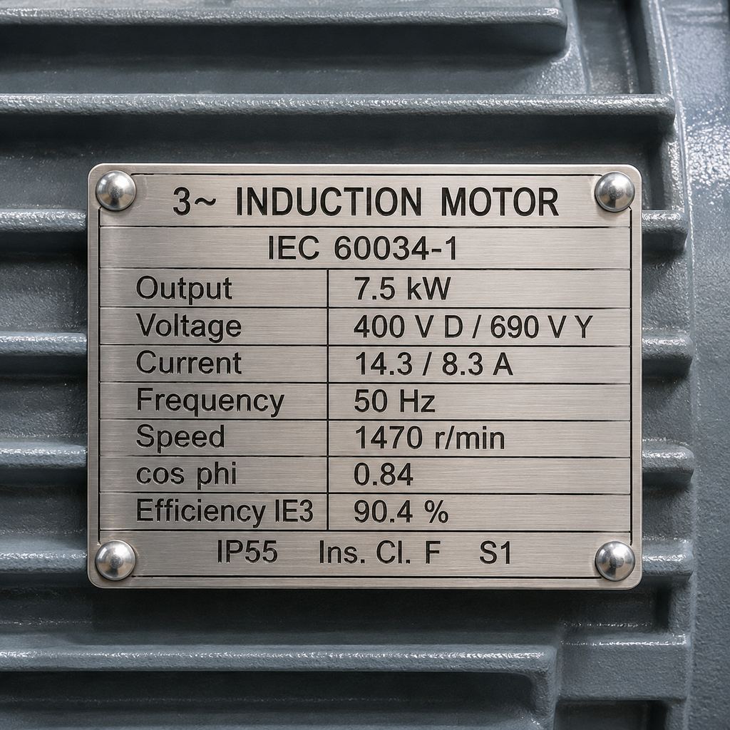
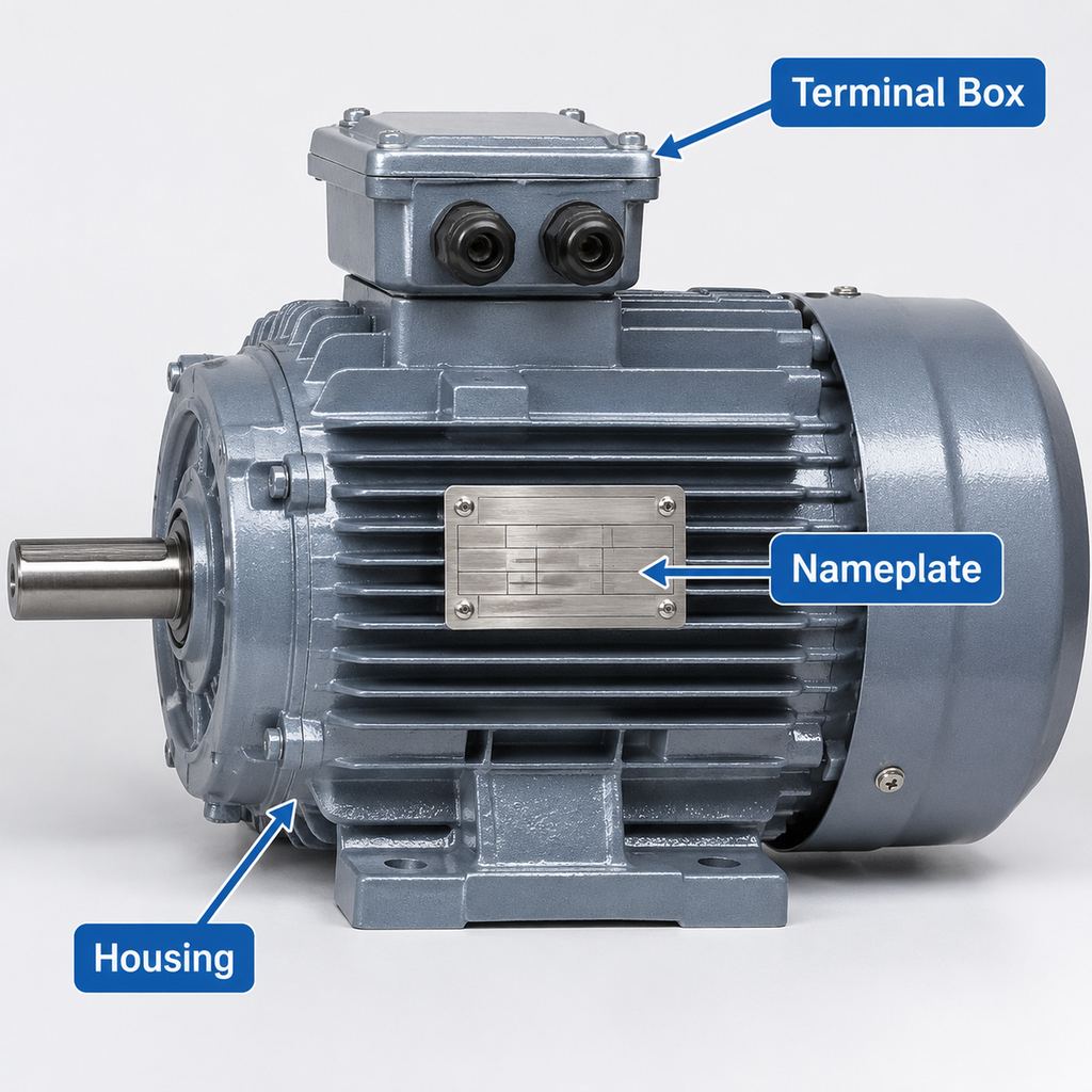
A typical IEC motor nameplate: output, voltage, rated current, cos φ and efficiency are all the data the FLC formula needs.
On a real motor, the rated current is already stamped on the nameplate. If you are not sure where to find it, see our guide on how to read an electric motor nameplate. The calculation below is what you use when the nameplate is missing, when you are planning before a motor is chosen, or when you want to check that a quoted current makes sense.
Formula for Calculating Full Load Current
The full load current (FLC) of a 3-phase motor can be calculated using the following formula:
I = P / (√3 × V × η × PF)
Where:
– I = Full load line current (in amperes)
– P = Motor rated output power at the shaft (in watts; multiply kW by 1,000, or hp by 746)
– V = Line-to-line supply voltage (in volts)
– η = Efficiency of the motor at full load (as a decimal, e.g., 92.1% efficiency is 0.921)
– PF = Power factor (cos φ) at full load (dimensionless, typically about 0.75 to 0.90 for standard induction motors; lower for small and slow, high-pole-count motors)
– √3 ≈ 1.732, the factor that links line-to-line voltage to three-phase power
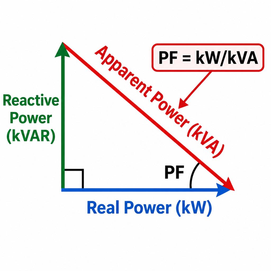
The formula comes from the three-phase power equation. Electrical input power is √3 × V × I × PF, and the shaft output is that input multiplied by efficiency. Solving for I gives the formula above. That is why both efficiency and power factor sit in the denominator: the motor draws more current than its output alone would suggest, because it must also cover its losses and its magnetizing (reactive) current. For more on the second term, see what electric power factor is.
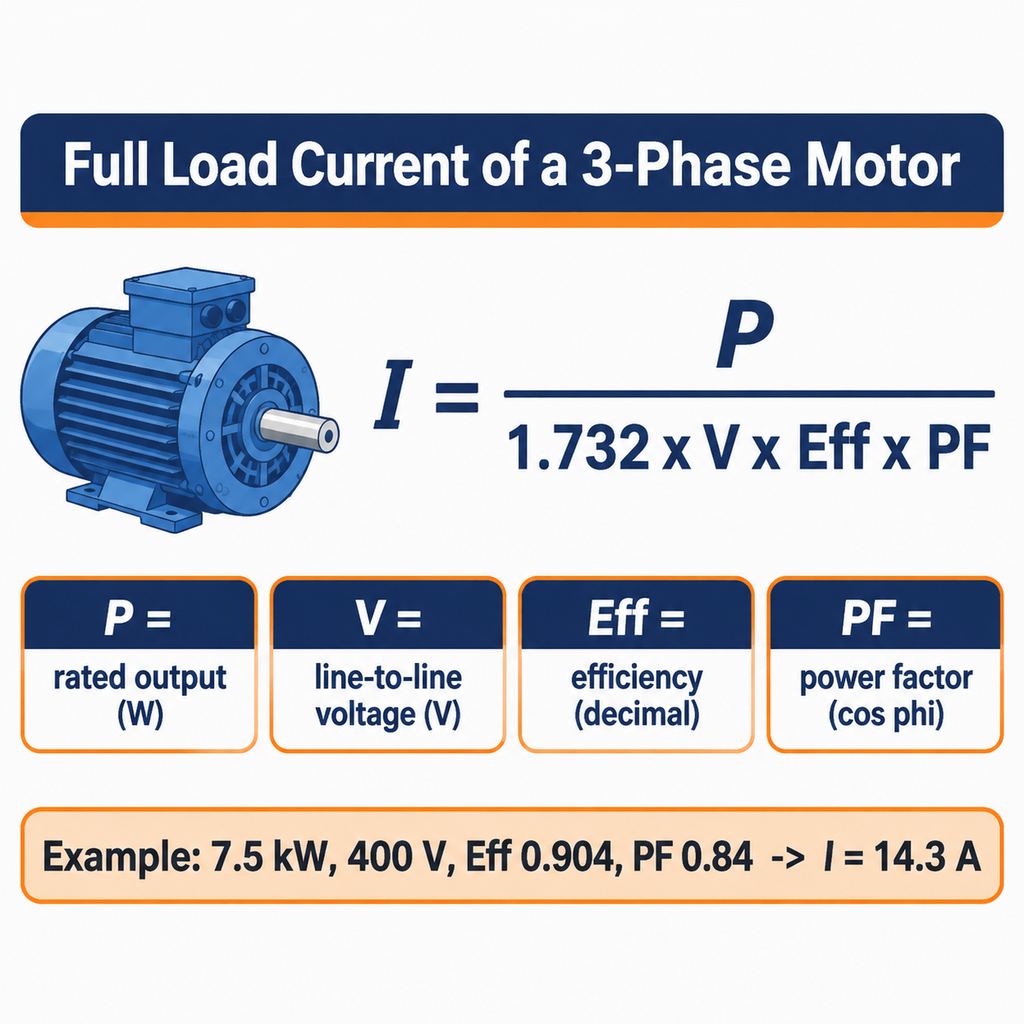
The FLC formula and a quick check: 7.5 kW, 400 V, η 0.904, PF 0.84 gives about 14.3 A.
As an example, let’s calculate the full load current for a 15 kW, 4-pole 3-phase motor at three common supply voltages. We assume an efficiency (η) of 92.1% (0.921) and a power factor (PF) of 0.86. These are typical values for a 4-pole IE3 motor of this size at 50 Hz (92.1% is the IEC 60034-30-1 IE3 minimum for 15 kW, 4-pole); they are illustrative, not a guarantee for any particular motor:
At 380 V:
I = 15,000 / (√3 × 380 × 0.921 × 0.86)
I = 15,000 / 521.3
I ≈ 28.8 A
At 400 V:
I = 15,000 / (√3 × 400 × 0.921 × 0.86)
I = 15,000 / 548.8
I ≈ 27.3 A
At 460 V:
I = 15,000 / (√3 × 460 × 0.921 × 0.86)
I = 15,000 / 631.1
I ≈ 23.8 A
The current falls in direct proportion as the voltage rises, because the same power is delivered at a higher voltage. Note that the 460 V line keeps the same η and PF only to show the effect of voltage; a motor actually rated 460 V is usually a 60 Hz design whose nameplate efficiency, power factor and current differ from the 50 Hz values.
It’s essential to note that the calculated current often differs slightly from the nameplate full load amperes (FLA). The nameplate value is the manufacturer’s declared current for that specific design at rated output, voltage and frequency, while the formula only uses the η and PF you assumed. Therefore, for a specific motor, use the nameplate or datasheet current, and treat the formula as an estimate and a cross-check.
Worked Examples of Full Load Current Calculation
Example 1: 22 kW, 4-pole motor at 380 V
Determine the full load current for a 22 kW, 4-pole motor on a 380 V supply, assuming an efficiency (η) of 93.0% (0.930) and a power factor (PF) of 0.86:
I = P / (√3 × V × η × PF)
I = 22,000 / (1.732 × 380 × 0.930 × 0.86)
I = 22,000 / 526.4
I ≈ 41.8 A
For comparison, our YE3-180L-4 (22 kW, 4-pole, IE3) lists exactly these values in the catalog: 93.0% efficiency, cos φ 0.86 and 41.8 A at 380 V. When η and PF are taken from the same datasheet, the formula reproduces the catalog current.
Example 2: the same motor at 400 V
I = 22,000 / (1.732 × 400 × 0.930 × 0.86)
I = 22,000 / 554.1
I ≈ 39.7 A
Example 3: the 690 V side of a 400/690 V motor
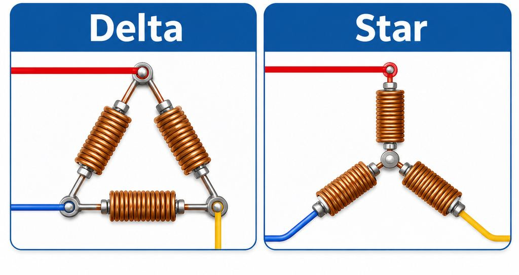
Find the current on the higher voltage of a 400/690 V dual-voltage motor (delta at 400 V, star at 690 V):
I = 22,000 / (1.732 × 690 × 0.930 × 0.86)
I = 22,000 / 955.9
I ≈ 23.0 A
This is the 400 V current divided by √3 (39.7 / 1.732 ≈ 22.9 A; the small difference is rounding). The formula always gives the line current, whichever connection is used.
Example 4: a horsepower-rated motor at 460 V
A 20 hp motor at 460 V, with a typical full-load efficiency of 93.0% and PF of 0.85:
P = 20 × 746 = 14,920 W
I = 14,920 / (1.732 × 460 × 0.930 × 0.85)
I ≈ 23.7 A
Difference Between Calculated and Nameplate FLC
Calculated full load current (FLC) often differs from the nameplate full load amps (FLA) specified on a motor. The formula, I = P / (√3 × V × η × PF), gives a current based on the efficiency and power factor you put into it, while the nameplate FLA is the current the manufacturer declares for that specific design at rated output, voltage and frequency.
The gap usually comes from the inputs, not the formula. Typical η and PF values are averages; the actual design of a given frame, pole count and supplier can be a point or two higher or lower. Nameplate values are also rounded, and standards such as IEC 60034-1 allow tolerances on declared efficiency and power factor. A lower PF or efficiency than assumed means a higher real current.
Operating conditions matter too. A motor running below its rated voltage draws more current for the same load, and a motor running at partial load draws less than its FLA. Measured current is therefore not the same thing as nameplate FLA, and neither is the starting current, which for direct-on-line starting is roughly 6 to 8.5 times rated current (see what happens to current when an induction motor starts).
For a specific motor, engineers and buyers should treat the nameplate or datasheet current as the definitive motor value when replacing an existing unit or setting its overload protection, and use the calculation as an estimate before the motor is selected or as a check that a quoted current is consistent with the quoted kW, voltage, η and PF.
The Role of Full Load Current in Cable and Protection Sizing
The full load current (FLC) of a 3-phase motor plays a fundamental role in determining the sizing of cables and protection devices. Cables must have sufficient cross-sectional area to carry the motor current continuously without overheating or excessive voltage drop, after corrections for ambient temperature, grouping and installation method. Undersized cables can lead to insulation breakdown, increased energy losses, or even fire hazards. The applicable wiring rules, such as IEC 60364 or the NEC, define how that sizing is done.
Which current value you start from depends on the rules that apply. In IEC-based practice, designers normally use the motor’s rated current from the nameplate or datasheet. Under the US National Electrical Code (NEC 430.6), conductor ampacity and branch-circuit short-circuit and ground-fault protection for general-purpose motors are based on the full-load current tables (for example Table 430.250 for three-phase motors), not on the nameplate, while separate overload protection is set from the nameplate FLA. The table values are deliberately conservative: Table 430.250 lists 27 A for a 20 hp, 460 V motor, compared with the roughly 23.7 A calculated above.
Protection devices, such as fuses, circuit breakers, motor circuit protectors and overload relays, safeguard the motor circuit by disconnecting power in case of overloads, short circuits or faults. Overload relays are set around the motor’s rated current, while short-circuit devices must also ride through the starting current. Our article on what a motor circuit protector is explains how FLA is used to set one. Inadequate sizing can result in frequent tripping or failure to protect.
In summary, FLC is not just a number from a formula but a practical reference for electrical system safety, efficiency and compliance. Correctly sized cables and protection based on the right current value help prevent downtime and extend both motor and system life. Final cable and protection selection should always follow the local electrical code and be done by a qualified designer.
Frequently Asked Questions
What is the difference between full load current and nameplate FLA?
Calculated full load current is an estimate of the current a motor draws at rated output, based on its rated power, voltage, and the efficiency and power factor you assume. Nameplate FLA (full load amps) is the current the manufacturer declares for that specific motor at rated output, voltage and frequency. When the two disagree, the nameplate value is the one that describes the actual motor.
Why does the motor nameplate FLA matter when sizing cables and protection devices?
The nameplate FLA indicates the current demand of that specific motor under full-load conditions. It is the basis for overload relay settings, and in IEC-based practice it is also the starting point for cable and protection sizing. Under the NEC, conductors and short-circuit protection for general-purpose motors are sized from the code’s FLC tables instead, while overloads are still set from the nameplate.
Can I use the same FLC formula for motors with variable speed drives (VSD)?
For the motor itself, yes: at its rated operating point the motor current is still the nameplate FLA. What changes is the current on the supply side of the drive, which depends on the drive’s own efficiency, its input power factor and harmonics. Drive input current, and the cable and protection upstream of the drive, should be taken from the drive manufacturer’s data. For background, see what a VFD drive is.