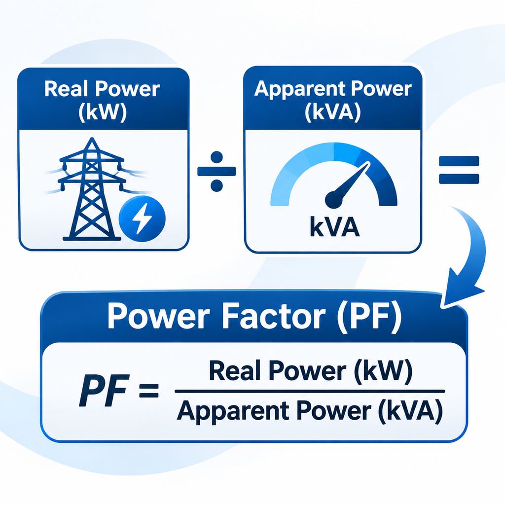
Electric power factor on a motor is the ratio of real (active) input power, in kilowatts (kW), to apparent power, in kilovolt-amperes (kVA). In symbols, PF = kW / kVA, which for a sinusoidal supply is also cos φ, where φ is the phase angle between voltage and current. It describes the motor as an electrical load. It is not the same as motor efficiency, which is shaft output divided by electrical input; that relationship is covered in how to determine motor efficiency and is not repeated here.
Industrial three-phase induction motors almost always have a lagging power factor: current lags voltage because the stator must draw magnetizing (reactive) current to establish the air-gap field. That reactive component is measured in kilovolt-amperes reactive (kVAR). It does not appear as shaft work, but it still flows in the supply and adds to the current the cables and transformer must carry.
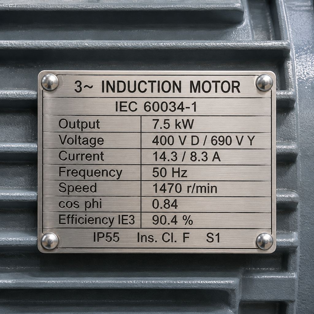
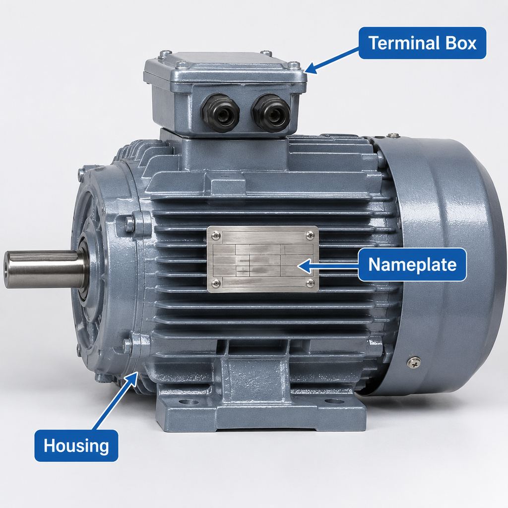
Unity power factor means PF = 1: voltage and current are in phase and there is no net reactive power. A squirrel-cage induction motor does not run at unity PF in normal industrial service. The nameplate figure is the full-load value, often marked PF or cos φ. How to find that marking is in how to read an electric motor nameplate; the short note below does not rewrite that guide.
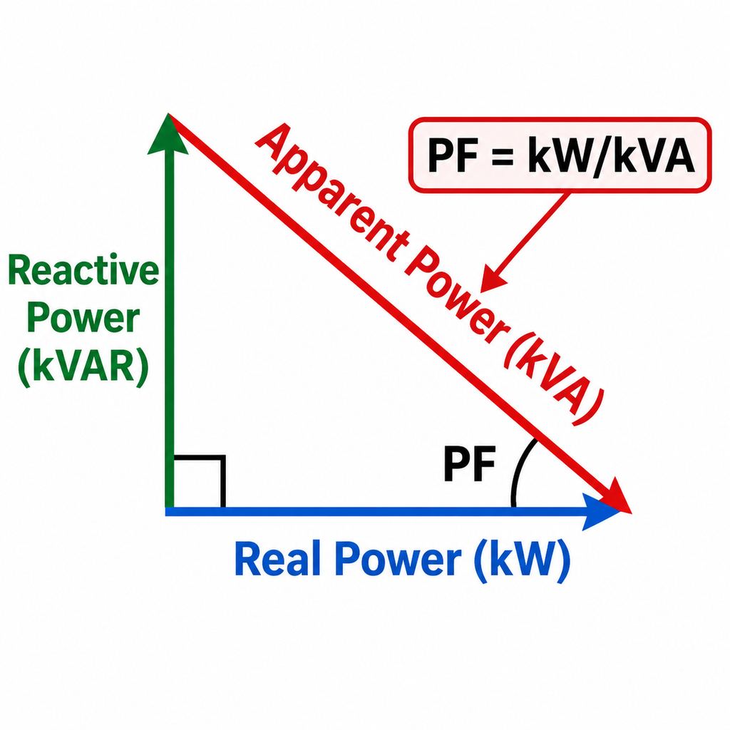
The Power Triangle: kW, kVAR and kVA
Real power, reactive power and apparent power form a right triangle. Real power (kW) is the horizontal side, reactive power (kVAR) is the vertical side, and apparent power (kVA) is the hypotenuse. The relationship is:
kVA² = kW² + kVAR², and PF = kW / kVA.
At unity power factor the vertical side is zero and kW equals kVA. As the lagging angle grows, kVAR rises, kVA grows for the same kW, and line current increases.
Why Induction Motors Have a Lagging Power Factor
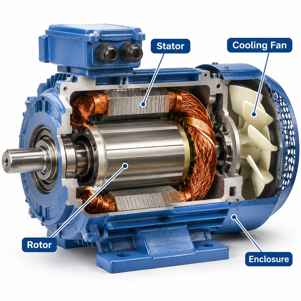
A squirrel-cage induction motor is an inductive load. A magnetizing current is required to produce flux in the iron and the air gap. That current is largely reactive, so the stator current lags the terminal voltage. The lag is a normal property of the machine, not a fault.
The magnetizing component does not shrink in proportion to shaft load. At full load, real power is high and nameplate PF is at its best. At light load or no-load, real power falls while a large share of the magnetizing current remains, so PF drops—often sharply. An oversized motor that spends most of its life well below its rated kW will therefore show a poorer operating power factor than the nameplate value. Sizing the motor to the duty is part of how to choose a 3-phase motor.
What Unity Power Factor Means
Unity power factor is PF = 1, or 100%. Current is in phase with voltage, reactive power is zero, and every kilovolt-ampere supplied is a kilowatt of real power. Resistive loads approach this condition; a standard induction motor does not. Synchronous machines can be excited toward unity or even a leading PF, but that is a different machine type and is not covered here.
Plant engineers sometimes correct a lagging motor load toward a higher system PF with capacitors. That is a site electrical-design choice. This article does not size capacitor banks. Raising the motor’s own full-load PF—by selecting a suitable high-efficiency induction motor and avoiding chronic underloading—reduces the reactive current the motor itself draws, but it does not replace a plant-level PF review where the utility tariff requires one.
What a Low Power Factor Does in the Plant
For a given shaft output, a lower PF means a higher line current, because the supply must deliver the same real power plus more reactive current. Three-phase input power is:
kW = √3 × V × I × PF / 1000
so, for a fixed kW and voltage, current I rises as PF falls. The extra current has three practical effects:
- Utility charges. Some industrial tariffs bill kVA demand or apply a power-factor penalty or adjustment. Where a threshold is used, it is often around 0.90 or 0.95, but the figure and the method belong to the local tariff—not to a universal rule, and not to a payback calculation in this article.
- Cable and transformer capacity. Conductors, switchgear and transformers are sized for apparent power and current, not only for kW. A cluster of lagging motors can use up feeder or transformer capacity that would otherwise be available for real load.
- I²R heating. Higher current increases losses in cables and in the supply transformers. Those are distribution losses, not a substitute for a motor-efficiency assessment.
Typical Nameplate PF and High-Efficiency Motors
The nameplate PF (or cos φ) is the full-load value at the rated voltage, frequency and output. It is not a guarantee of the PF you will measure at part load.
As a typical published pattern for three-phase induction motors at full load, smaller machines often show a nameplate PF in the mid-0.8s, and many larger 4-pole motors are nearer 0.9. No-load PF is much lower. These are typical catalogue-style figures, not guarantees for any particular rating, and not a substitute for the value printed on the nameplate or in the series data sheet.
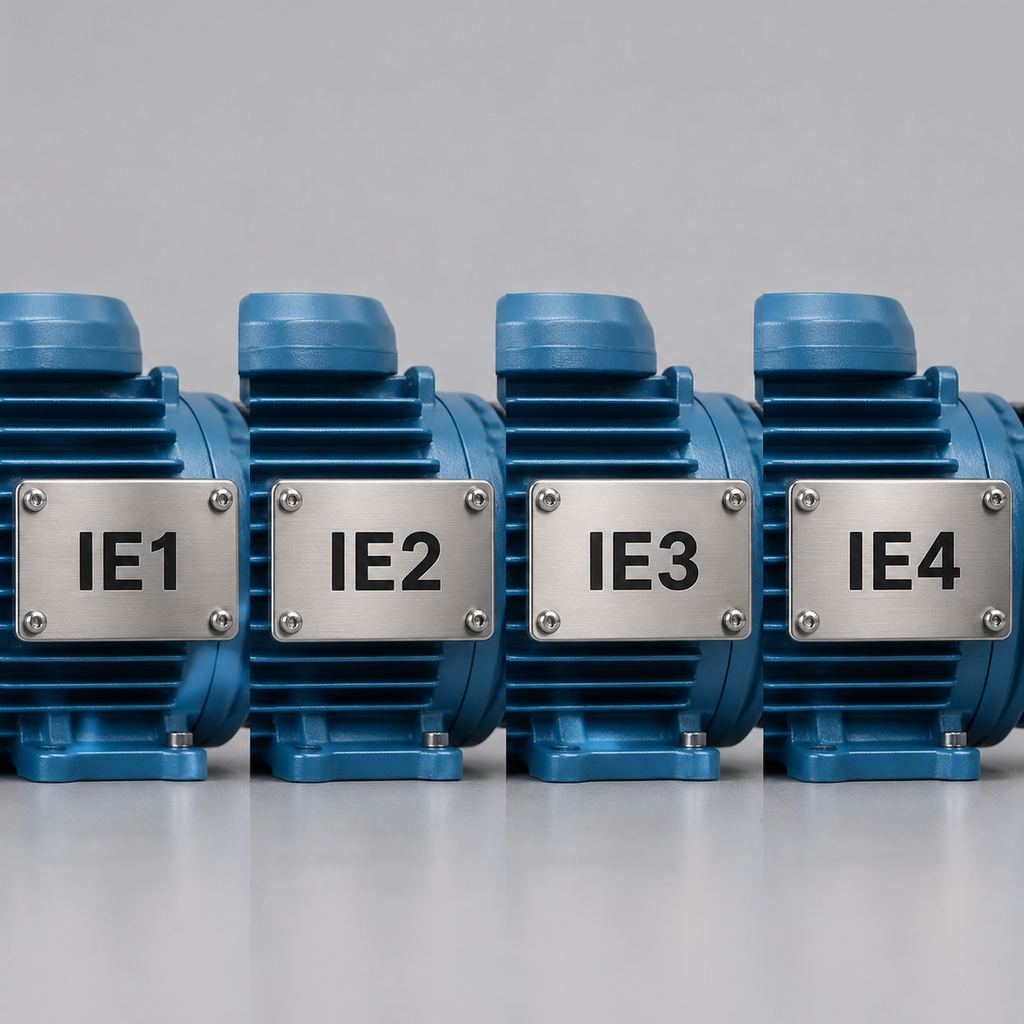
Higher-efficiency designs such as IE3 and IE4 often have a slightly better full-load PF than older IE1 or IE2 motors of the same rating and speed. That is a typical tendency, not a guaranteed increment, and it still falls if the motor is oversized. The IE classes themselves, and why IE1 and many IE2 applications are being phased out, are explained in IE2 vs IE3 vs IE4 (Y2, YE3, YE4), the comparative analysis of IE2, IE3 and IE4 motors, and what is IE1. This page does not retell those articles. YE3 and YE4 are the IE3 and IE4 induction ranges discussed there.
How to Calculate Motor Power Factor
Do not rearrange the input-power formula to “find” kW from a PF you do not yet know; that is circular. The straightforward plant method is:
- Measure real input power (kW). Use a power meter or analyzer on the motor supply. If you only know shaft output and efficiency, electrical input kW = shaft kW / η. Efficiency must come from a tested or nameplate value; it is not interchangeable with PF.
- Measure line voltage and line current, then calculate apparent power. For a three-phase motor, kVA = √3 × V × I / 1000, with V the line-to-line voltage and I the line current (use the mean of the three lines if they differ).
- Divide. PF = kW / kVA. The result is a decimal between 0 and 1, sometimes written as a percentage (0.85 = 85%).
- Optional check. On a sinusoidal supply, PF should also equal cos φ from a meter that reports the voltage–current phase angle.
On a consistent nameplate, rated current, voltage, output, efficiency and PF hang together:
I = Pout / (√3 × V × η × PF)
If a quoted current cannot be reconciled with those quantities, treat the data as incomplete rather than inventing a missing number.
FAQ
What is electric power factor on a motor?
It is the ratio of real input power (kW) to apparent power (kVA), also written as cos φ. It tells you how much of the volt-amperes drawn by the motor is real power. It is not motor efficiency.
What is a unity power factor?
Unity means PF = 1: current in phase with voltage and no net reactive power. Standard industrial induction motors operate at a lagging PF below unity, including at full load.
What does a PF of 0.8 mean?
A PF of 0.8 means real power is 80% of apparent power: kW = 0.8 × kVA. Because of the right triangle, reactive power is 0.6 × kVA (since 0.8² + 0.6² = 1), not 20% of kVA. The “remaining 20%” is not the kVAR share.
Why do induction motors lag?
They draw reactive magnetizing current to produce the air-gap field, so current lags voltage. The lag increases as load falls.
Does a better power factor save a fixed percentage on the electricity bill?
Not as a generic figure. kWh charges follow real energy, which tracks load and efficiency. A higher PF mainly reduces current and kVA demand, and it may reduce a tariff penalty where one applies. No saving percentage or payback is stated here; use the site’s measured load and the actual tariff.
If You Are Specifying an IE3 or IE4 Motor
When you are replacing an older IE1 or IE2 machine, or specifying a new three-phase motor, start from the YE3 (IE3) or YE4 (IE4) ranges listed under general-purpose motors. Use the nameplate or data sheet PF for the exact rating; do not assume a catalogue typical. For a non-standard voltage, shaft or mounting, see customization or all products.