
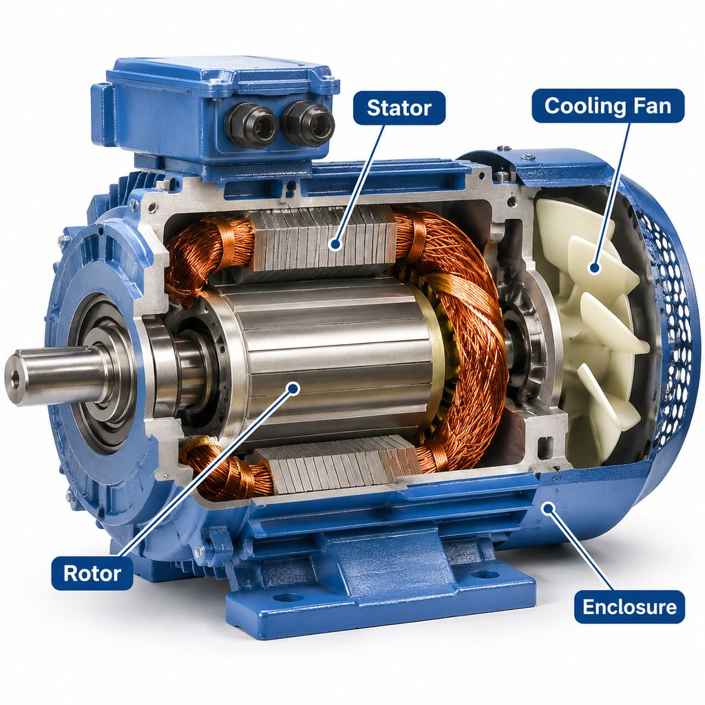
A motor winding is the insulated conductor system that carries current and creates the magnetic field. In a three-phase induction motor, buyers and maintenance teams usually mean the stator winding: coils of magnet wire placed in the stator core slots, grouped into three phases and brought out to the terminal box. The rotor may also have a winding (wound-rotor designs) or a squirrel-cage bar-and-ring assembly; this article focuses on the stator winding in general-purpose industrial motors.
Understanding windings helps when a motor fails electrically, when you compare copper constructions and insulation systems, and when you decide whether to rewind or replace. Winding burnouts are a common end mode of motor failure; for the broader failure picture, see what is the most common cause of motor failure.
What a Stator Winding Is Made Of
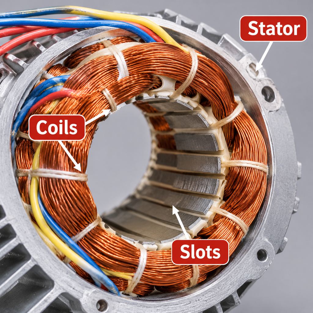
- Magnet wire (coil wire): enamel-insulated copper or aluminum conductors forming the turns of each coil.
- Coils: groups of turns shaped to fit the stator bore; several coils in series/parallel make one phase.
- Slots: openings in the laminated stator core that locate the coil sides and provide magnetic coupling to the air gap.
- Slot and phase insulation: slot liners, separators, phase paper and impregnating varnish or resin that separate conductors from the core and from each other.
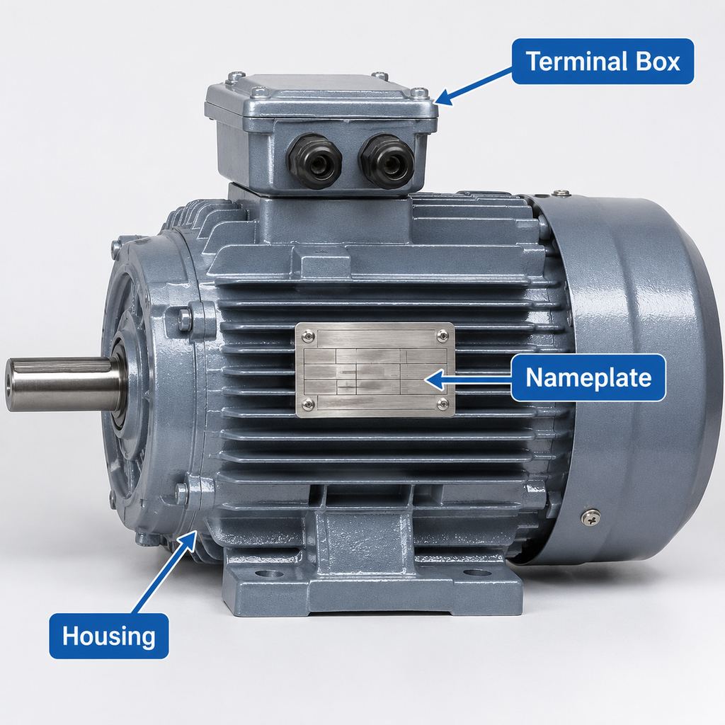
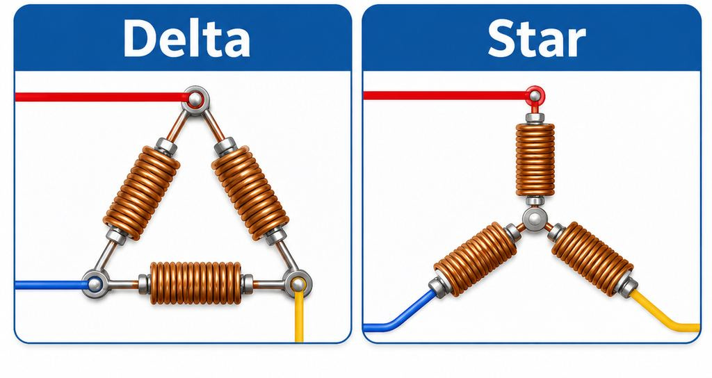
- Leads and terminals: the ends of the three phases (commonly labeled U, V, W or T1–T6 on dual-voltage machines) brought into the terminal box for star or delta connection.
Together these parts are “the winding.” A coil is one building block; a winding is the complete connected assembly for the machine.
How a 3-Phase Stator Winding Is Built (Overview)
The stator core is a stack of electrical-steel laminations with evenly spaced slots. Coils are inserted into those slots so that each of the three phases occupies a symmetrical set of positions around the bore. That geometry produces a rotating magnetic field when the phases are supplied 120 electrical degrees apart.
After insertion, coils are connected into phase groups. Dual-voltage industrial motors often bring out six leads so the same winding can be connected in star or delta for the two rated voltages. Connection practice belongs in the wiring guide for three-phase electric motors—this article does not repeat those terminal diagrams.
The winding is then impregnated (varnish or resin) and cured so conductors are locked against vibration and moisture. Insulation class and temperature rise limits define how hot the winding may run in continuous service; see insulation class.
Distributed vs Concentrated Windings
| Arrangement | What it means | Where it shows up |
|---|---|---|
| Distributed | Coil sides of each phase are spread over several slots, producing a smoother field | Standard three-phase induction motors (pumps, fans, conveyors) |
| Concentrated | Coils are concentrated around fewer teeth/slots | Selected compact or specialty machines; not the usual YE3/YE4 layout |
For plant buyers specifying cast-iron general-purpose motors, assume a distributed stator winding unless the datasheet says otherwise.
Copper vs Aluminum Magnet Wire
Copper has higher conductivity than aluminum for the same cross-section, so copper windings typically allow lower I²R loss and support higher efficiency designs. Aluminum can reduce conductor cost and weight but needs a larger cross-section for similar resistance and careful joint practice. Premium-efficiency industrial lines such as YE3 and YE4 are generally copper-wound; confirm the conductor material on the quotation if the project specifies it. Material context: copper in motors.
Conductor choice interacts with efficiency and temperature rise. Lower winding loss is one reason a correctly loaded high-efficiency motor runs cooler; see motor efficiency.
Insulation Class and Temperature Rise
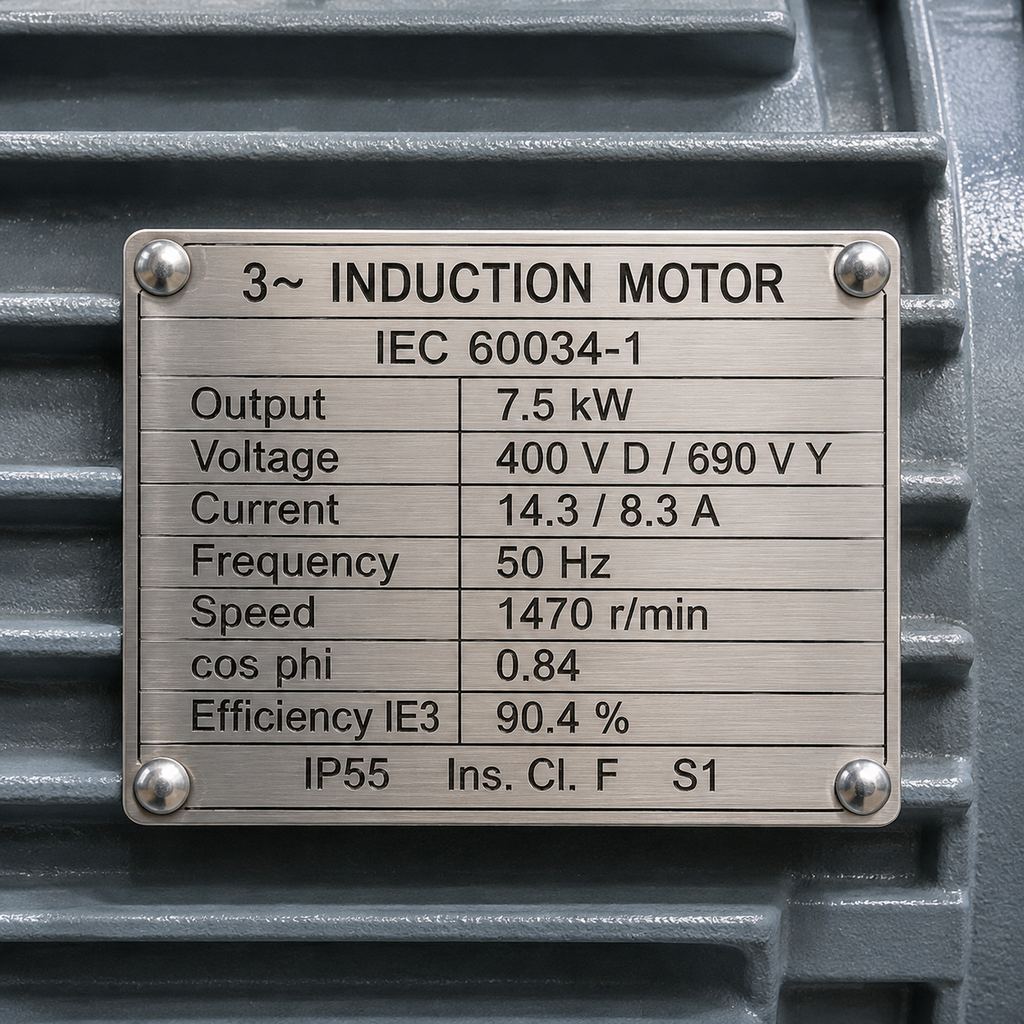
Insulation systems are classified by the maximum hot-spot temperature they are designed to withstand (for example Class F). Temperature rise is how much the winding is allowed to heat above a reference ambient under rated load. Many YE3/YE4 designs use a Class F insulation system with a Class B temperature rise: the insulation can tolerate a higher hot-spot, while the design rise is held lower to leave thermal margin.
That margin helps when ambient is warm or cooling is imperfect, but it does not authorize continuous overload or single-phasing. Phase loss still overheats windings quickly; see single phasing of a motor.
How to Rewind a Motor—What a Shop Does (Not DIY)
“How to rewind a motor” in an industrial setting means sending the machine to a qualified service center. It is not a field DIY job: stripping, core testing, coil manufacture, insulation and impregnation need controlled processes and equipment.
Typical shop overview:
- Inspect and document nameplate data, connection and damage.
- Cut and remove the old winding; clean the slots.
- Check the stator core for hot spots, burns or looseness (a damaged core is a reason to replace, not rewind).
- Manufacture new coils to the recorded or redesigned winding data.
- Insulate slots, insert coils, make connections and bring out leads.
- Impregnate and cure; assemble, balance as required and test.
Before authorizing a rewind, insulation condition may be screened with an insulation resistance test—procedure overview: how to meg a 3-phase motor.
Rewind vs Replace: Cost and Efficiency Trade-offs
| Factor | Rewind (repair winding) | Replace with new motor |
|---|---|---|
| Best fit | Large, special or long-lead motors; core and mechanics still sound | Standard IEC frames in stock; old low-efficiency machines; damaged core/frame |
| Cost pattern | Often lower than new for large/special machines; labor-heavy on small motors | Higher purchase price; may avoid repair uncertainty |
| Efficiency | A best-practice rewind can maintain original efficiency; a poor rewind can increase losses | Opportunity to move to IE3/IE4 and cut energy use on long-running duties |
| Downtime | Depends on shop queue; may beat a long new-motor lead time | Fast if the correct frame is in stock; mounting checks still required |
| Risk | Depends on shop quality and core condition | New warranty; verify mechanical and electrical interchangeability |
Rewind tends to make sense when the stator core is healthy, the motor is large or customized, a quality shop can match the original winding data and the repaired efficiency is acceptable for the remaining life.
Replacement tends to make sense when the motor is a common small/medium frame, repair approaches new cost, the existing efficiency is poor on a high-hour duty, or the core/frame/bearings are also compromised.
Compare lifecycle energy cost as well as invoice price. Use the motor selection checklist so a replacement matches load, duty, mounting and environment—not only kW.
Specifying Windings on New YE3/YE4 Motors
For new continuous-duty pumps, fans and conveyors, cast-iron YE3/YE4 motors in the general-purpose motors range are typically supplied with copper stator windings and a Class F insulation system (often with Class B rise). If you need special winding connections, space heaters, PTC thermistors or non-standard leads, request them through customization rather than assuming a catalog motor includes them.
FAQ
What is a motor winding?
The insulated coil system that carries current. In three-phase induction motors this usually means the stator winding in the slotted core.
What is the difference between a coil and a winding?
A coil is a set of turns; a winding is the complete connected set of coils for the machine or for one phase.
Can any burned motor be rewound?
No. If the core is burned, loose or shorted, or the frame/shaft is damaged, replacement is usually the better path.
Does rewinding always reduce efficiency?
Not necessarily. Industry best-practice rewinds aim to maintain original efficiency. Poor process control can raise losses—choose the shop carefully and require documented winding data.


2 thoughts on “What Is a Motor Winding? Coils, Insulation and Rewind vs Replace”