Introduction to Three-Phase Electric Motors
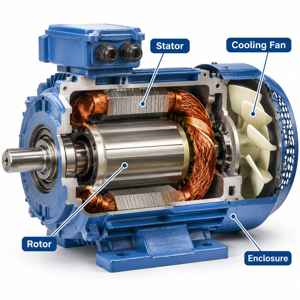
Three-phase electric motors are a cornerstone of industrial and commercial operations due to their highly efficient and robust performance. These motors are primarily designed for applications that demand consistent, high power, such as pumps, compressors, conveyors, and industrial machinery. Unlike single-phase motors, which rely on a single alternating current, three-phase motors utilize three separate currents to create a rotating magnetic field. This design not only provides smoother and more efficient torque but also allows for a more compact motor that can handle heavy-duty tasks with greater reliability.
Understanding how to wire a three-phase electric motor is critical, as improper wiring can lead to performance inefficiencies, motor damage, or even safety risks. Before proceeding with the wiring process, it is essential to have a clear understanding of the motor’s terminal configurations, power supply requirements, and protection features. This article will guide you through the fundamental principles and practical steps for safely and efficiently wiring a three-phase motor to meet your application’s requirements.
Understanding the Basics of Motor Wiring
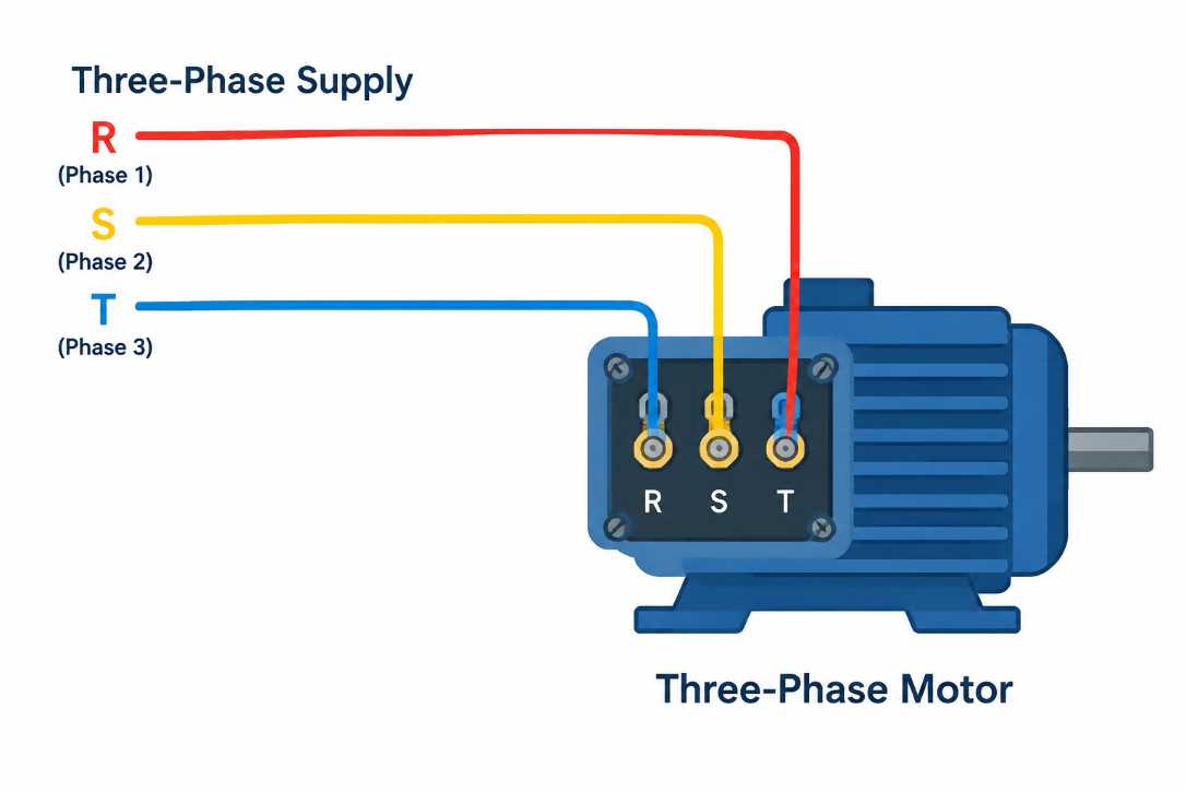
At its core, wiring a three-phase electric motor involves connecting the motor’s three terminals to a compatible power supply. To understand this process better, it’s essential to familiarize yourself with key wiring concepts and terminology. These foundational elements not only ensure a safe connection but also optimize the motor’s performance.
Key Concepts in Three-Phase Motor Wiring:
- Three-Phase Power Supply: A three-phase system consists of three alternating currents (phases), each 120 degrees out of sync with the others. This structure produces a continuous, smooth torque, which is ideal for powering industrial motors.
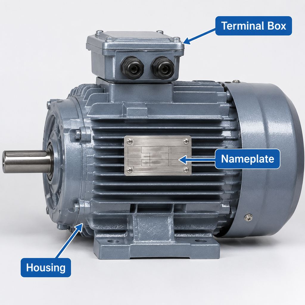
- Motor Terminal Configuration: Most three-phase motors include terminals labeled T1, T2, and T3, which correspond to the phases. Some motors also feature additional terminals (e.g., T4, T5, T6) for flexible wiring configurations, such as star or delta connections.
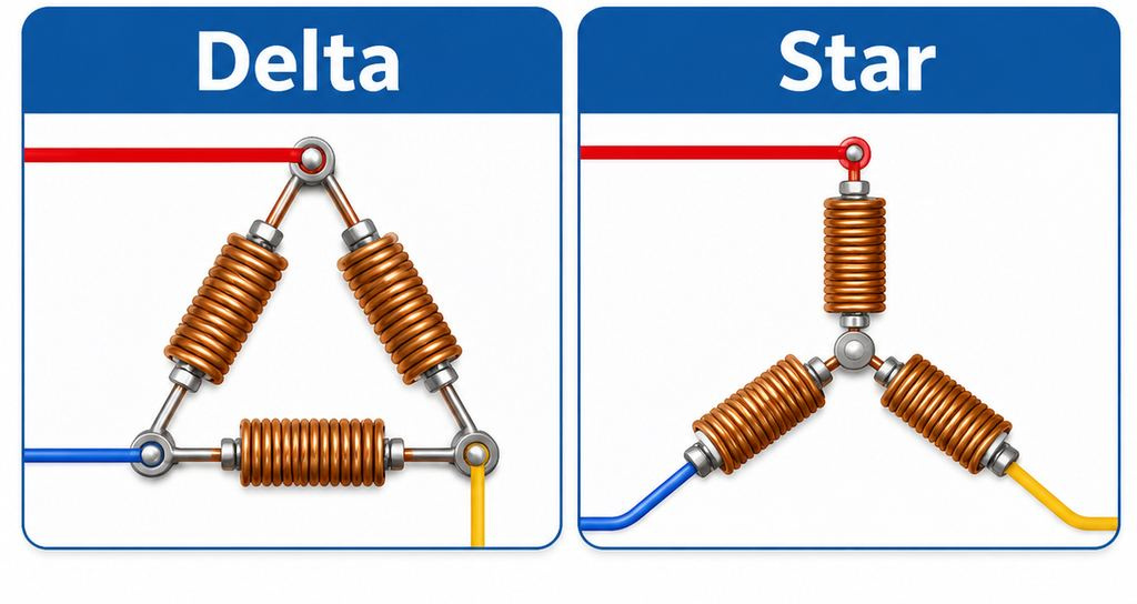
- Star (Wye) vs. Delta Connection: These are the two primary methods of connecting motor windings to the power supply. A star configuration groups windings to handle lower voltage, often used during starting, while a delta configuration is designed for full-load operation at higher voltage levels.
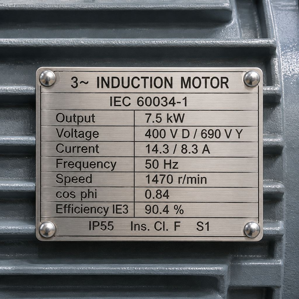
- Voltage and Current Ratings: Matching the motor’s voltage rating with the supply voltage is critical. For example, a 400V motor in Europe should be connected to a 400V three-phase supply. Any discrepancy could lead to performance issues or motor damage.
- Protective Devices: Circuit breakers, fuses, and overload relays are essential to safeguard the motor against overcurrent, short circuits, or overheating. These should be rated according to the motor’s specifications.
Terminology to Know:
- Line-to-line voltage: The voltage measured between any two of the three phases.
- Phase sequence: The order in which the power phases are connected to the motor; an incorrect sequence may cause the motor to run in reverse.
- Insulation class: A measure of the motor winding’s ability to withstand heat—crucial for long-term durability.
By developing a clear understanding of these wiring basics, engineers and purchasers can not only ensure safe installations but also select the correct accessories and configurations for their specific applications.
Step-by-Step Guide to Wiring a Three-Phase Electric Motor
- Ensure all power sources are disconnected before beginning any electrical work. Confirm the absence of electrical current using a reliable voltage tester to avoid risks of electrical shock.
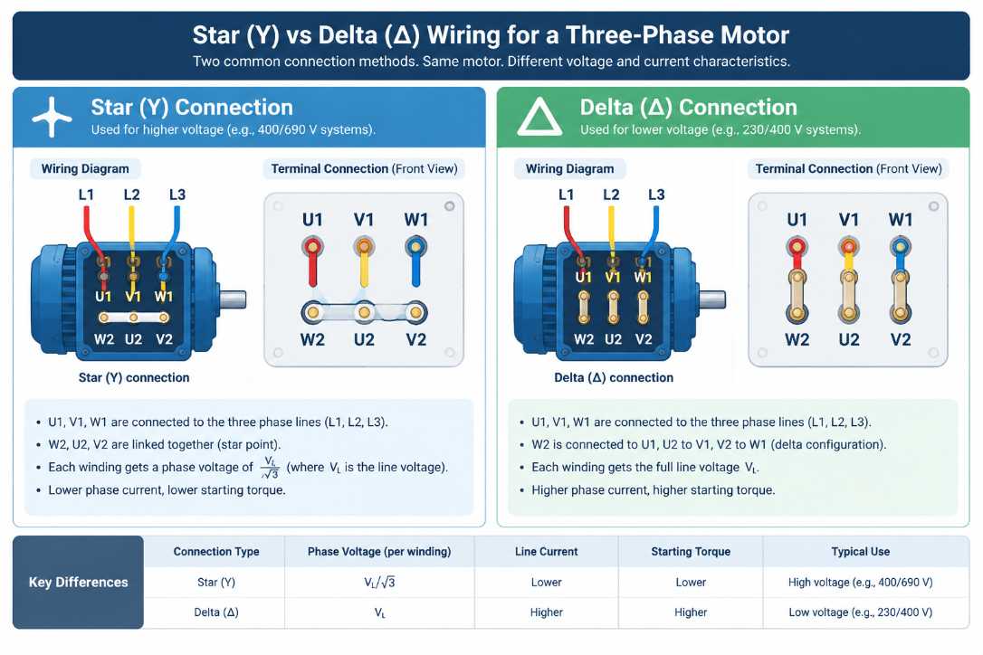
- Identify and confirm the wiring configurations on the motor’s terminal plate. Most three-phase motors are equipped with six terminals, commonly labeled T1, T2, T3, T4, T5, and T6, which are configured to support both star (wye) and delta connections.
- Select the connection type — star or delta — based on the voltage available from your power supply. Typically, star connections are used for higher voltage levels, while delta configurations are fit for lower voltage applications.
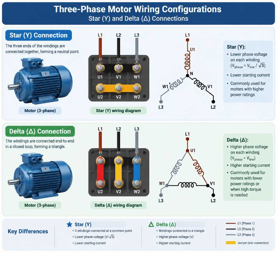
- Connect the three power supply lines (L1, L2, L3) to the corresponding terminals on the motor (T1, T2, T3). For star wiring, connect T4, T5, and T6 together as the neutral point. For delta wiring, connect T1 to T6, T2 to T4, and T3 to T5.
- Inspect all connections to ensure they are tightened securely and insulated properly. Loose or poorly insulated connections can lead to inefficient performance and potential safety hazards.
- Attach any required external components, such as a thermal relay or overload protection device. These devices enhance safety by safeguarding the motor against overheating or power surges.
- Once all wiring is completed, perform a continuity test using a multimeter to verify that the connections are correct and free of faults. This step is crucial before turning the motor on.
- Power on briefly and observe the motor’s rotation direction. If the rotation is incorrect, swap any two of the phase wires to change direction, a feature unique to three-phase motors.
Key Wiring Diagrams and Their Interpretations
- Star (Wye) Connection Diagram: This is a common wiring configuration used when a motor operates at a higher voltage level. The three ends of the windings (T4, T5, T6) are connected together at a single point called the neutral, forming the shape of the letter “Y” or “star”. The power supply is then connected to the other ends of the windings (T1, T2, T3). This setup ensures lower inrush currents during startup, making it suitable for applications requiring a gentle start-up or where the power supply is restricted.
- Delta Connection Diagram: In this arrangement, each motor winding is connected end-to-end to form a closed triangle, with the three corners connected to the power supply (phases L1, L2, L3). The delta connection is often employed in low-voltage, high-power applications to provide maximum performance and efficiency during continuous operation. Without a neutral point, this wiring boosts the motor’s ability to deliver greater torque compared to the star configuration.
Frequently Asked Questions about Wiring Three-Phase Motors
How do I wire up a 3-phase motor?
To wire a 3-phase motor, you must connect the three supply phases to the motor’s corresponding terminals (commonly labeled T1, T2, and T3). Depending on the voltage requirements and motor configuration, you will choose between a star (Wye) connection for higher starting torque or a delta connection for optimal continuous operation. Always consult the motor’s nameplate and wiring diagram for precise connections.
Does 3-phase require 4 wires?
Typical 3-phase motors require three wires for the phases. However, certain wiring systems may use a fourth wire if a neutral connection is needed, such as in some star (Wye) configurations or for auxiliary purposes. Always verify your system’s requirements and motor type.
How many wires go to a 3-phase motor?
The number of wires going to a 3-phase motor usually depends on its configuration. Most motors feature three wires corresponding to the three power phases. Motors with dual voltage capabilities or advanced wiring options may have six wires to accommodate star or delta configurations. Confirm the actual wiring needs based on the motor’s terminal label and detailed diagrams.
How to wire a 3-phase plug with 4 wires?
Wiring a 3-phase, 4-wire plug generally involves connecting three wires for the phases (L1, L2, L3) and one neutral or ground wire. Ensure that the socket configuration matches your motor setup and that the connections align with safety codes. Double-check correct phase orientation for proper motor operation.
Safety Considerations and Electrical Wiring Guidelines
Wiring a three-phase electric motor involves working with high voltages and requires strict adherence to safety protocols. Before beginning any electrical work, always ensure that all power sources to the motor and associated electrical panels are disconnected and locked out using a reliable lockout/tagout (LOTO) system. Verify the absence of electrical power using a multimeter or voltage tester.
Additionally, always consult the motor’s nameplate and technical documentation for proper voltage, current, and connection instructions. Incorrect wiring can damage the motor, compromise safety, and void the manufacturer’s warranty. Ensure that all tools and safety equipment, such as insulated gloves and footwear, are appropriate for the task.
Another critical aspect is understanding local electrical codes and standards, such as UL/NEC in the United States or IEC standards in Europe. These guidelines ensure compliance with essential safety and operational requirements. For example, you may need to use circuit protection devices like fuses, circuit breakers, or overload relays to prevent electrical hazards such as short circuits, phase imbalance, or overloading.
If you are unsure about any aspect of the wiring process, consult a licensed electrician or a qualified technician. Always prioritize safety and double-check all connections prior to applying power to the circuit.