Motor mounting is how an electric motor is fixed to the driven machine and how the shaft is oriented in service. For IEC industrial motors the arrangement is ordered with an IM (International Mounting) code such as B3, B5 or B35. Power and speed alone are not enough for an RFQ: the mounting code, frame size, shaft and flange dimensions must match the machine interface.
This guide is a practical selection overview of common IEC mounting types for three-phase cast-iron motors. For the broader standards landscape, see Understanding IEC Electric Motors. For the full selection sequence, use the motor selection checklist and RFQ guide.
Foot Mount vs Flange Mount Motor
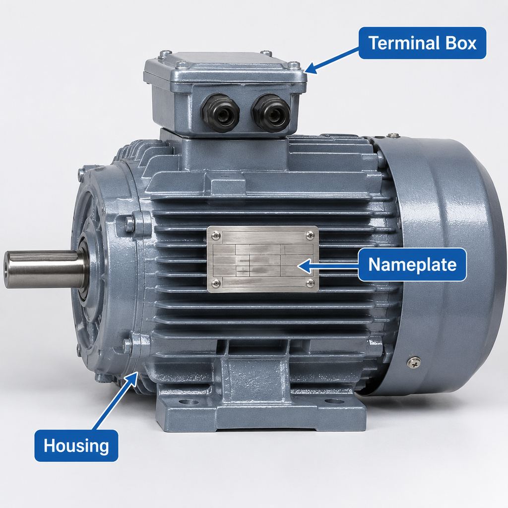
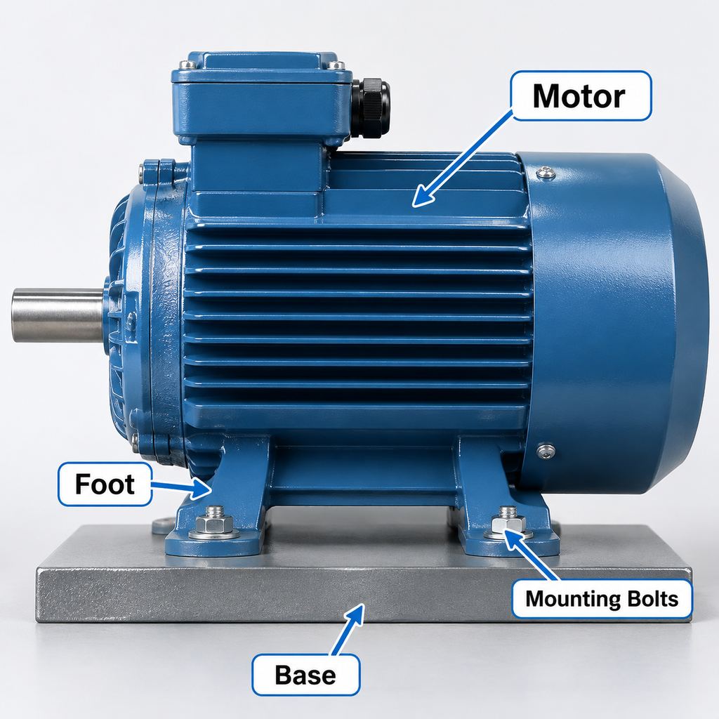
A foot-mounted motor sits on cast feet bolted to a base, bedplate or frame. A flange-mounted motor is located by a circular drive-end flange that bolts to the driven machine (pump, fan housing or gearbox). Some motors combine both interfaces. “Foot” and “flange” describe the fixing method; the IEC letter-number code also states shaft orientation.
IEC Motor Mounting Types (IM Codes)
| Code | Fixing | Shaft orientation | What to remember |
|---|---|---|---|
| B3 | Feet only | Horizontal | Most common base-mounted arrangement |
| B5 | Large flange (clearance holes) | Horizontal | Motor carried by the flange; no feet |
| B14 | Small face flange (tapped holes) | Horizontal | Compact flange; hole type differs from B5 |
| B35 | Feet + large flange | Horizontal | Both interfaces present; check which carries the load |
| V1 | Large flange | Vertical, shaft down | Common on vertical pumps |
| V5 | Feet | Vertical, shaft down | Foot-fixed with shaft down; confirm bracket design |
Catalogs may also list related codes (for example B34 for feet plus small flange, or V3 for flange with shaft up). Always read the supplier’s IM designation together with the dimensional drawing—do not assume two “flange motors” are interchangeable.
B3 vs B5 vs B35
- B3 (foot mount): Choose when the machine provides a flat base and the drive uses a coupling, belt or separate gearbox input. Easy to align on a bedplate; foot-hole spacing must match the drawing.
- B5 (large flange): Choose when the driven equipment presents a matching large flange face. The flange locates the motor; there are no feet. Confirm pilot diameter, bolt circle, clearance holes and face runout requirements from the catalogue.
- B35 (foot + flange): Choose when the design needs both a base support and a flange interface, or when stock flexibility is required. Do not force-fit bolts to correct mismatched faces—verify both interfaces on the drawing.
B14 is the compact counterpart to B5: smaller flange, typically with tapped fixing holes. Specifying only “flange mounted” is ambiguous—state B5 or B14 explicitly.
Which Mounting Suits Which Equipment
| Equipment | Common starting point | Check before ordering |
|---|---|---|
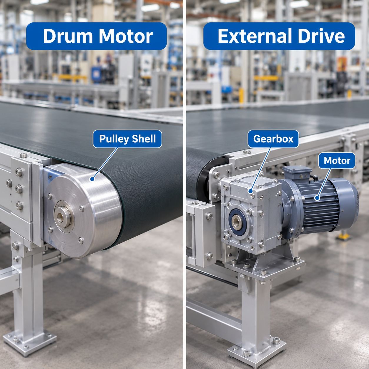
| Base-mounted pumps, conveyors, belt drives | B3 | Foot spacing, shaft height, coupling/belt alignment |
| Close-coupled pumps, flanged fan housings, many gearboxes | B5 (or B14 on smaller machines) | Flange type, pilot, bolt circle, shaft extension |
| Machines needing base support plus flange location | B35 | Which interface takes weight and which locates the shaft |
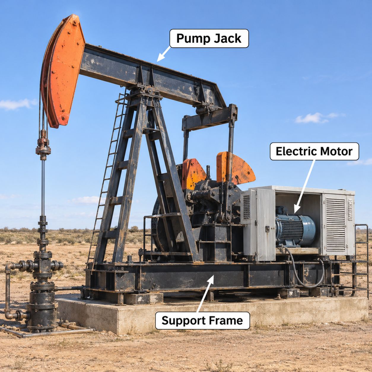
| Vertical pumps / mixers with shaft down | V1 | Axial thrust, bearing arrangement, drains, canopy if outdoor |
Gear reducers often take a flanged motor or use an integrated gear-motor package. For reducer selection context see what is a gear motor; mounting of R/F/K/S units follows the gearbox output and motor interface stated on that product drawing, not a generic B-code alone. Browse gear motors when the machine needs reduced shaft speed.
Frame Size, Shaft Extension and Flange Size
IEC frame size sets the mechanical envelope: shaft centre height for foot motors, shaft diameter and extension, and the matching flange family for that frame. Larger frames use larger shafts and flanges, but exact millimetres vary by series and options.
Refer to the catalogue or certified dimensional drawing for every RFQ. Do not scale dimensions from photographs or from another brand’s frame chart. When replacing a motor, compare the old drawing or measure the installed interface—and confirm terminal-box position and shaft key size as well as the IM code.
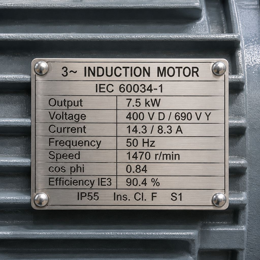
Nameplate data may show mounting or frame information; reading practice is covered in how to read an electric motor nameplate.
Vertical Mounting: Bearings and Protection
Vertical service changes the load on the bearings. Rotor weight and any external axial thrust from pumps or mixing shafts act along the shaft axis. Tell the supplier the magnitude and direction of thrust, duty cycle and lubrication method. Bearing arrangement options are discussed under motor bearings—do not assume a standard horizontal bearing fit is automatically correct for V1/V5.
Also review condensation drains (orientation changes where water collects), cooling airflow, lifting method, terminal-box access and, for outdoor vertical machines, weather protection such as a canopy. Ingress rating and canopy needs should be stated in the RFQ alongside the IM code.
How to State Mounting in an RFQ
Copy and complete:
- IM / mounting code (e.g. IM B3, IM B5, IM B35, IM V1)
- IEC frame size and series interest (e.g. YE3 / YE4 / Y2—availability of each mounting to be confirmed)
- Shaft orientation in service (horizontal / shaft down / shaft up)
- Driven machine interface (base, large flange, small flange) and drawing number if available
- Required flange designation if known (and whether clearance or tapped holes)
- Shaft extension, key and any second shaft end
- Terminal-box position viewed from the drive end
- External axial/radial loads and vertical thrust if any
- Environment: indoor/outdoor, IP requirement, canopy or drains
Cast-iron YE3, YE4 and Y2 motors in the general-purpose motors range are offered in several mounting arrangements depending on frame and order configuration—confirm the specific model’s options on the quotation. Non-standard box positions or flanges can be requested via customization.
For how mounting fits the wider product map, see three-phase motor types, applications and series selection.
FAQ
What is motor mounting?
The mechanical arrangement that fixes the motor and orients the shaft—expressed for IEC motors by an IM code such as B3 or B5.
B3 vs B5 vs B35—which do I need?
B3 for base/foot mounting, B5 for large-flange mounting without feet, B35 when both feet and a large flange are required. Match the machine drawing, not only the application name.
Is B14 the same as B5?
No. B14 uses a smaller face flange, typically with tapped holes. Always specify which flange type the driven equipment needs.
Can any horizontal motor be installed vertically?
Not without checking bearings, lubrication, drains and the supplier’s approved IM codes. Order the vertical arrangement you will actually use.