A motor frame size chart links an IEC or NEMA frame designation to the mechanical dimensions that decide whether a motor fits a machine: shaft centre height, foot-hole spacing, shaft diameter and extension, and flange size where one is used. Below are the standard IEC dimensions for frames 56–355, NEMA dimensions for frames 48–449T, the shaft-height rules, and an IEC-to-NEMA equivalence table.
Frame size confirms mechanical fit only. Power, speed, voltage, frequency and duty still have to come from the nameplate and the supplier’s datasheet.
What a Motor Frame Size Chart Tells You
The U.S. Department of Energy’s Premium Efficiency Motor Selection and Application Guide defines frame size as a set of physical motor dimensions established by NEMA for interchangeability between manufacturers. IEC does the same for metric motors. In both systems, the frame designation is a shorthand for a standard set of mounting dimensions, not a complete description of the motor.
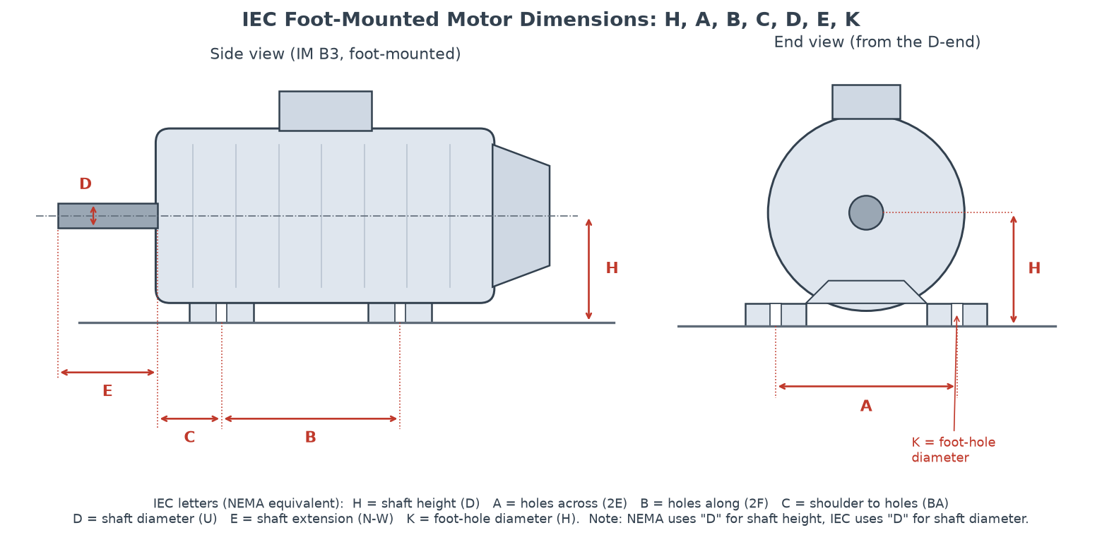
The dimensions you will see on almost every chart are:
- H (IEC) / D (NEMA): shaft height. The distance from the bottom of the feet to the shaft centreline. This is the dimension the frame number is built on.
- A (IEC) / 2E (NEMA): foot holes across the motor, measured between hole centres at right angles to the shaft.
- B (IEC) / 2F (NEMA): foot holes along the motor, parallel to the shaft. Longer frames of the same height have a larger B.
- C (IEC) / BA (NEMA): distance from the shaft shoulder at the drive end to the centreline of the nearest foot holes.
- K (IEC) / H (NEMA): diameter of the foot holes or slots.
- D × E (IEC) / U and N-W (NEMA): shaft diameter and usable shaft extension length.
Watch the letter D. In IEC drawings, D is the shaft diameter. In NEMA drawings, D is the shaft height and the shaft diameter is U. The letter H also swaps meaning: IEC shaft height versus NEMA hole size. Always read the legend on the drawing before comparing two charts.
IEC charts also show the mounting arrangement, coded under IEC 60034-7: IM B3 (foot-mounted), IM B5 (large flange, no feet), IM B14 (small face flange) and IM B35 (feet plus flange). The same frame number can be built in any of these, so the mounting code is part of the specification. For a plain foot motor, see JW’s overview of B3 foot-mounted motors.
IEC Motor Frame Size Chart (Frames 56–355)
For IEC motors, the frame number is the shaft height in millimetres: a 132M motor has H = 132 mm. The letter after the number is a length code: S (short), M (medium) or L (long). It changes the foot spacing B, not the height. The A, B, C and K values below are the foot-mounted (IM B3) fixing dimensions from IEC 60072-1. Shaft sizes are common manufacturer practice and are given separately for 2-pole and 4-pole-and-above motors where they differ.
| Frame | H | A | B | C | K | Shaft D × E, 2-pole | Shaft D × E, 4-pole and up |
|---|---|---|---|---|---|---|---|
| 56 | 56 | 90 | 71 | 36 | 5.8 | 9 × 20 | 9 × 20 |
| 63 | 63 | 100 | 80 | 40 | 7 | 11 × 23 | 11 × 23 |
| 71 | 71 | 112 | 90 | 45 | 7 | 14 × 30 | 14 × 30 |
| 80 | 80 | 125 | 100 | 50 | 10 | 19 × 40 | 19 × 40 |
| 90S | 90 | 140 | 100 | 56 | 10 | 24 × 50 | 24 × 50 |
| 90L | 90 | 140 | 125 | 56 | 10 | 24 × 50 | 24 × 50 |
| 100L | 100 | 160 | 140 | 63 | 12 | 28 × 60 | 28 × 60 |
| 112M | 112 | 190 | 140 | 70 | 12 | 28 × 60 | 28 × 60 |
| 132S | 132 | 216 | 140 | 89 | 12 | 38 × 80 | 38 × 80 |
| 132M | 132 | 216 | 178 | 89 | 12 | 38 × 80 | 38 × 80 |
| 160M | 160 | 254 | 210 | 108 | 14.5 | 42 × 110 | 42 × 110 |
| 160L | 160 | 254 | 254 | 108 | 14.5 | 42 × 110 | 42 × 110 |
| 180M | 180 | 279 | 241 | 121 | 14.5 | 48 × 110 | 48 × 110 |
| 180L | 180 | 279 | 279 | 121 | 14.5 | 48 × 110 | 48 × 110 |
| 200L | 200 | 318 | 305 | 133 | 18.5 | 55 × 110 | 55 × 110 |
| 225S | 225 | 356 | 286 | 149 | 18.5 | not usually built | 60 × 140 |
| 225M | 225 | 356 | 311 | 149 | 18.5 | 55 × 110 | 60 × 140 |
| 250M | 250 | 406 | 349 | 168 | 24 | 60 × 140 | 65 × 140 |
| 280S | 280 | 457 | 368 | 190 | 24 | 65 × 140 | 75 × 140 |
| 280M | 280 | 457 | 419 | 190 | 24 | 65 × 140 | 75 × 140 |
| 315S | 315 | 508 | 406 | 216 | 28 | 65 × 140 | 80 × 170 |
| 315M | 315 | 508 | 457 | 216 | 28 | 65 × 140 | 80 × 170 |
| 315L | 315 | 508 | 508 | 216 | 28 | 65 × 140 | 80 × 170 |
| 355M | 355 | 610 | 560 | 254 | 28 | 75 × 140 | 95 × 170 or 100 × 210 |
| 355L | 355 | 610 | 630 | 254 | 28 | 75 × 140 | 95 × 170 or 100 × 210 |
All dimensions in mm. A = holes across, B = holes along, C = shaft shoulder to nearest holes, K = foot-hole diameter.
Notes on reading the IEC table:
- K values. IEC 60072-1 lists 14.5 mm holes for frames 160–180 and 18.5 mm for 200–225. Many catalogues print these rounded to 15 and 19 mm.
- Shafts from frame 225 up. Two-pole motors usually have a smaller shaft than 4-pole motors in the same frame because they deliver less torque per kW. On frame 355, the 4-pole shaft varies by manufacturer, and some makers use different shaft sizes in other frames too. Treat the shaft columns as typical values and confirm them on the drawing.
- Overall length (L) is not standardised. It differs between manufacturers and between IE2, IE3 and IE4 designs in the same frame. Many suppliers also offer non-preferred variants such as 112S or 250S, so a full catalogue may list more frames than this table.
You can look up the shaft height for common frames with JW’s IEC frame and shaft height lookup.
NEMA Motor Frame Size Chart (Frames 48–449T)
NEMA frames are used mainly in the United States and Canada. Two-digit frames (42, 48, 56) cover small, mostly fractional-horsepower motors. Three-digit T frames cover integral-horsepower motors. The third digit indicates foot length (2F), so 143T and 145T share a shaft height but have different foot spacing. The values below are the standard NEMA MG 1 foot-mounted dimensions in inches.
| Frame | D (shaft height) | 2E | 2F | BA | U (shaft dia.) | N-W (shaft length) |
|---|---|---|---|---|---|---|
| 48 | 3 (76.2 mm) | 4-1/4 | 2-3/4 | 2-1/2 | 1/2 | 1-1/2 |
| 56 | 3-1/2 (88.9 mm) | 4-7/8 | 3 | 2-3/4 | 5/8 | 1-7/8 |
| 143T / 145T | 3-1/2 (88.9 mm) | 5-1/2 | 4 / 5 | 2-1/4 | 7/8 | 2-1/4 |
| 182T / 184T | 4-1/2 (114.3 mm) | 7-1/2 | 4-1/2 / 5-1/2 | 2-3/4 | 1-1/8 | 2-3/4 |
| 213T / 215T | 5-1/4 (133.35 mm) | 8-1/2 | 5-1/2 / 7 | 3-1/2 | 1-3/8 | 3-3/8 |
| 254T / 256T | 6-1/4 (158.75 mm) | 10 | 8-1/4 / 10 | 4-1/4 | 1-5/8 | 4 |
| 284T / 286T | 7 (177.8 mm) | 11 | 9-1/2 / 11 | 4-3/4 | 1-7/8 | 4-5/8 |
| 324T / 326T | 8 (203.2 mm) | 12-1/2 | 10-1/2 / 12 | 5-1/4 | 2-1/8 | 5-1/4 |
| 364T / 365T | 9 (228.6 mm) | 14 | 11-1/4 / 12-1/4 | 5-7/8 | 2-3/8 | 5-7/8 |
| 404T / 405T | 10 (254 mm) | 16 | 12-1/4 / 13-3/4 | 6-5/8 | 2-7/8 | 7-1/4 |
| 444T / 445T / 447T / 449T | 11 (279.4 mm) | 18 | 14-1/2 / 16-1/2 / 20 / 25 | 7-1/2 | 3-3/8 | 8-1/2 |
Dimensions in inches unless shown. 2E = holes across, 2F = holes along (one value per frame in the row), BA = shaft shoulder to nearest holes.
The Hydraulic Institute’s NEMA motor frame dimension reference tool lists the same frame dimensions and notes that the D dimension on rigid-base motors is held to +0.00 / −0.06 inch. Two suffix details matter when ordering:
- TS frames (for example 284TS or 364TS) keep the feet and shaft height of the T frame but have a shorter, often smaller shaft, intended for direct coupling. Do not swap a T and a TS motor without checking the shaft.
- C, D and other suffixes add a face or flange (for example 184TC). Older U frames used the same frame numbers with smaller shafts than today’s T frames, so a 254U and a 254T motor are not interchangeable at the shaft.
How to Calculate Shaft Height from a Motor Frame Size
You can read the nominal shaft height straight from most frame numbers. NEMA’s motor mounting types guide gives the rules for integral-horsepower and fractional-horsepower frames.
- IEC frames: the number is the height. Frame 160L means H = 160 mm from the bottom of the feet to the shaft centreline. Ignore the S/M/L letter for height; it only changes B.
- NEMA three-digit frames: first two digits ÷ 4 = D in inches. For a 184T: 18 ÷ 4 = 4.5 in (114.3 mm). For the largest common T frame, 449T: 44 ÷ 4 = 11.0 in (279.4 mm). The third digit relates to the foot spacing 2F, and the suffix letters to shaft and mounting variants.
- NEMA two-digit frames: frame number ÷ 16 = D in inches. A 48 frame has D = 48 ÷ 16 = 3.0 in. A 56 frame has D = 56 ÷ 16 = 3.5 in (88.9 mm). This is why a NEMA 56 motor is not a 56 mm shaft-height motor.
- Check the result against the drawing. The rule gives the nominal height. Shims, adapter bases and non-standard designs change the installed height, so confirm D or H on the manufacturer’s dimensional drawing before machining a base.
IEC vs NEMA Frame Equivalents
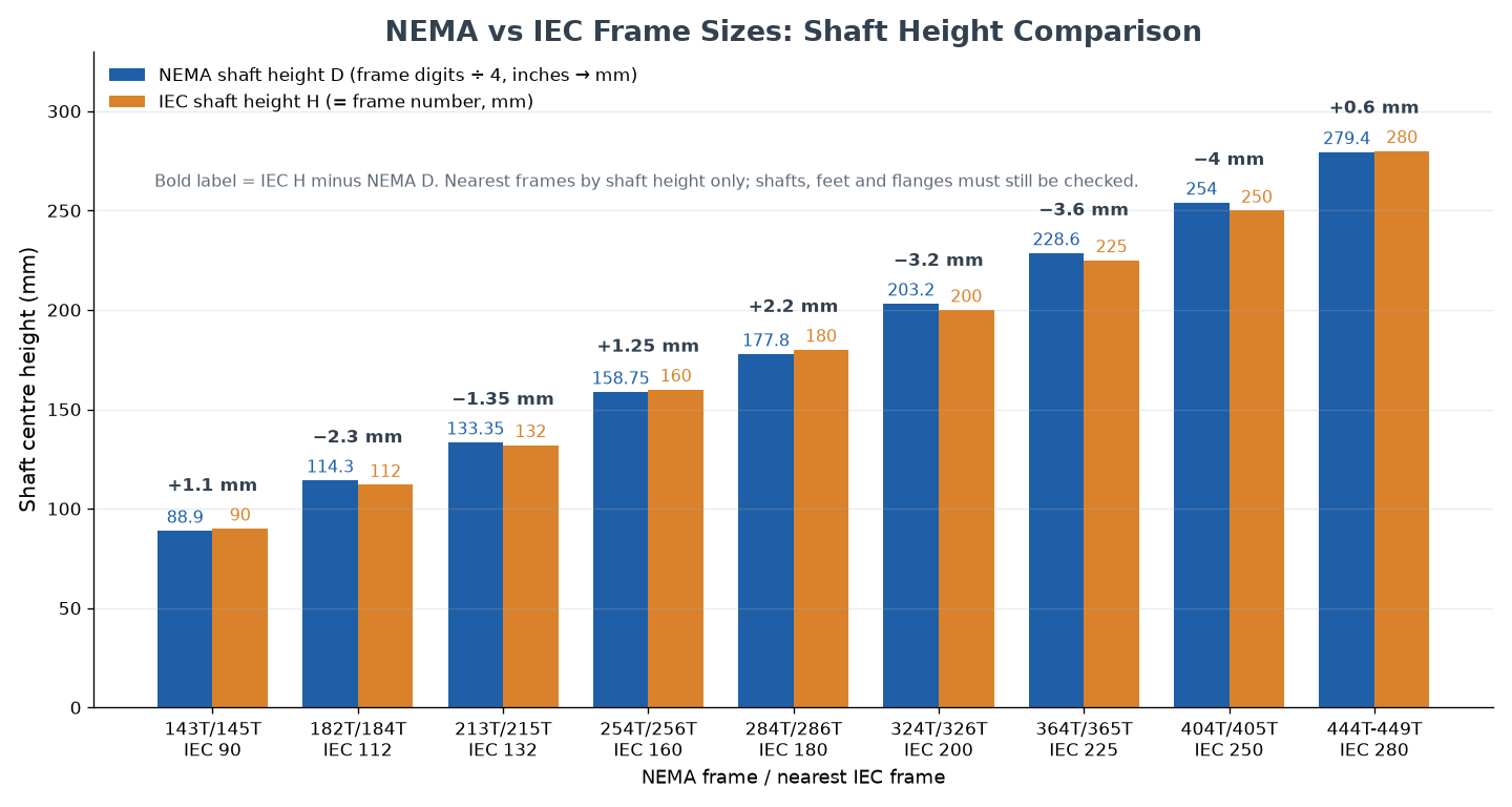
NEMA and IEC each guarantee interchangeability within their own system, not between them. The table pairs each common T frame with the IEC frame of nearest shaft height. From 184T up, several pairs also have foot spacings within about a millimetre, but the shafts never match exactly.
| NEMA frame | NEMA shaft height | Nearest IEC frame | IEC shaft height | Height difference (IEC − NEMA) | NEMA shaft U vs typical IEC shaft D |
|---|---|---|---|---|---|
| 143T / 145T | 88.9 mm | 90S / 90L | 90 mm | +1.1 mm | 22.2 mm vs 24 mm |
| 182T / 184T | 114.3 mm | 112M | 112 mm | −2.3 mm | 28.6 mm vs 28 mm |
| 213T / 215T | 133.35 mm | 132S / 132M | 132 mm | −1.35 mm | 34.9 mm vs 38 mm |
| 254T / 256T | 158.75 mm | 160M / 160L | 160 mm | +1.25 mm | 41.3 mm vs 42 mm |
| 284T / 286T | 177.8 mm | 180M / 180L | 180 mm | +2.2 mm | 47.6 mm vs 48 mm |
| 324T / 326T | 203.2 mm | 200L | 200 mm | −3.2 mm | 54.0 mm vs 55 mm |
| 364T / 365T | 228.6 mm | 225S / 225M | 225 mm | −3.6 mm | 60.3 mm vs 55–60 mm |
| 404T / 405T | 254 mm | 250M | 250 mm | −4.0 mm | 73.0 mm vs 60–65 mm |
| 444T–449T | 279.4 mm | 280S / 280M | 280 mm | +0.6 mm | 85.7 mm vs 65–75 mm |
Practical consequences of the mismatch:
- Shaft height is never identical. A 1–4 mm difference has to be taken up with shims or a new base, and the coupling must be realigned.
- Shafts need new bores or bushings. An inch shaft such as 1-1/8 in (28.58 mm) will not fit a 28 mm j6 coupling half without rework, and on large frames the gap reaches 10 mm or more.
- Flanges do not carry over. NEMA C-face (TC) bolt circles and IEC FF/FT flanges are different series.
- Some frames have no partner. IEC 56, 63, 71, 100, 315 and 355 have no NEMA T frame of matching height.
| Criterion | NEMA | IEC |
|---|---|---|
| Frame number means | Shaft height code: first two digits ÷ 4 (or ÷ 16 for two-digit frames), in inches | Shaft height H in millimetres |
| Governing standard | NEMA MG 1 | IEC 60072-1 (dimensions), IEC 60034-7 (mounting codes) |
| Main markets | United States, Canada | Europe, Asia and most other regions |
| Shaft dimensions | U and N-W fixed per frame (T or TS) | D × E, often different for 2-pole and 4-pole |
| Mounting variants | Suffix letters such as T, TS, TC | IM codes such as B3, B5, B14, B35 |
Using the Chart to Specify a Replacement Motor
A frame chart is the right tool for shortlisting. It is not enough to approve a purchase. A good replacement specification has three parts: mechanical fit, electrical and load suitability, and installation clearance.
Mechanical fit. Record the full frame designation and mounting code, then measure shaft height, foot-hole pattern, shaft and key, plus pilot and bolt circle on flange motors.
Couplings and belts. On a base-mounted pump, the shaft extension must accept the existing coupling hub and leave room for alignment. A longer motor body can fit the base yet hit nearby pipework or the guard. For belt drives, ask the supplier to confirm the allowable radial load for your pulley diameter and belt tension. Frame size alone says nothing about bearing capacity.
Efficiency upgrades. Moving from IE2 to IE3 or IE4 usually keeps the IEC frame and foot dimensions. However, the motor can be longer and heavier because of the extra active material. Check overall length, fan-cover clearance, terminal-box position and lifting access.
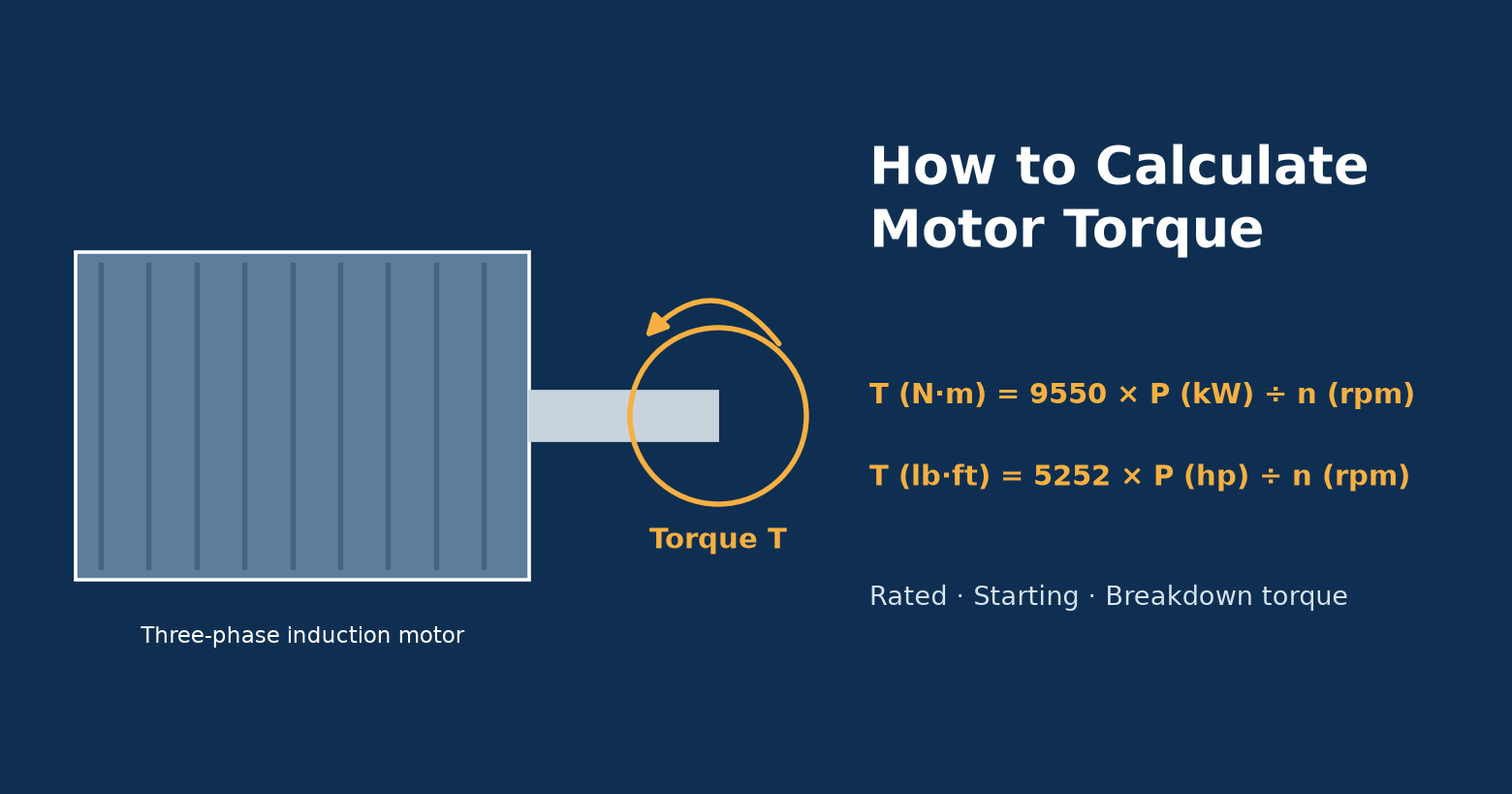
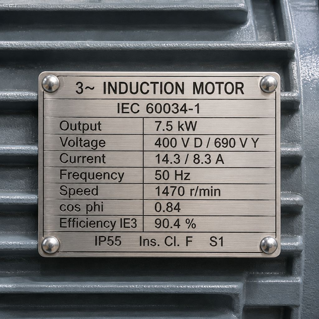
Electrical and load data. Confirm rated output, speed, voltage, frequency, duty and enclosure from the nameplate, and check that the starting torque suits the load. To check what torque a given power and speed delivers, use the method in JW’s guide on how to calculate motor torque. For imported IEC machinery in North America, confirm the motor’s voltage and 60 Hz rating explicitly rather than assuming them.
JW’s YE3 series (IE3) three-phase induction motors follow IEC 60072 frame dimensions. Each frame page lists the A, B, C, H, D and E values for every model. When requesting a quote, send the nameplate photo, the mounting code and the measured interface dimensions, and ask for the dimensional drawing of the exact configuration offered.
Where to Find Reliable Frame Dimension Data
IEC dimensions come from IEC 60072-1:2022, which covers the relationships between frame size, shaft extensions, rated outputs and flange numbers. NEMA dimensions come from NEMA MG 1. For a specific purchase, the manufacturer’s drawing of the exact model is the final reference: it is the only document that shows overall length, terminal-box position and accessories such as brakes or encoders. Use distributor charts only if they state units, suffix definitions and a revision date.
FAQ on Motor Frame Size Charts
How do I use a motor frame size chart to select a replacement?
Identify the standard, read the full frame designation and mounting code, and compare shaft height, foot holes, shaft and flange dimensions. Confirm the electrical rating separately.
What does the number in an IEC motor frame size mean?
It is the shaft centre height in millimetres. Frame 132 means 132 mm from the bottom of the feet to the shaft centreline. The letter S, M or L that follows is the frame length, which changes the foot spacing B.
How do I find the shaft height of a NEMA frame?
For three-digit frames, divide the first two digits by 4 to get inches: 184T gives 4.5 in and 449T gives 11.0 in. For two-digit frames, divide the frame number by 16: 48 gives 3.0 in and 56 gives 3.5 in.
Are IEC and NEMA motor frame sizes interchangeable?
Not directly. Some pairs, such as 184T and IEC 112M, have nearly identical foot spacing, but shaft heights differ by 1–4 mm and the shafts differ in diameter and length. A swap normally needs shims or a new base, a new coupling bore and realignment.
Can a motor frame size chart tell me the motor’s kW rating?
Only approximately. IEC 60072-1 links standard rated outputs to each frame size and pole count for enclosed induction motors, so a frame suggests a typical power range. For example, JW’s YE3 frame 132 models cover 2.2–7.5 kW across 2- to 8-pole versions. The exact rating must still come from the nameplate or datasheet.
What do the T and TS suffixes on a NEMA frame mean?
T identifies the current standard NEMA dimensions for integral-horsepower motors, which replaced the older U frames and gave many frames a larger shaft. TS is the short-shaft version of the same frame, mainly used for direct-coupled loads.
Will a JW IE4 motor fit the same space as an IE2 or IE3 motor?
JW’s YE4 (IE4) motors use IEC frame sizes and foot dimensions, so the mounting interface usually carries over in the same frame. The motor can be longer or heavier, so check the dimensional drawing and the available clearance before ordering.
Conclusion
A motor frame size chart answers one question well: will the motor bolt in and line up? IEC frame numbers give the shaft height in millimetres; NEMA T frames give it in inches (first two digits ÷ 4). Use the tables to shortlist, the IEC↔NEMA table to judge the rework a cross-standard swap needs, and the supplier’s dimensional drawing to approve the motor.