A brake motor is an electric motor with a brake built onto it, so the same unit that drives a load can also stop it and hold it in place. In industrial equipment the brake is almost always an electromagnetic, spring-applied design that engages automatically whenever power is removed. This guide explains what a brake motor is, how electric motor brakes work, how a brake motor differs from a standard motor, where it is used, and what to check when selecting one.
What Is a Brake Motor?
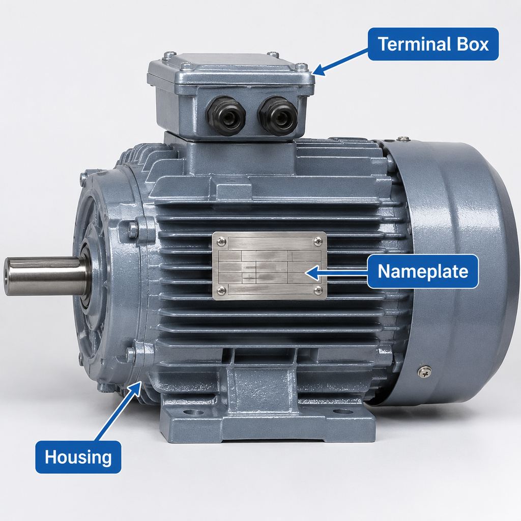
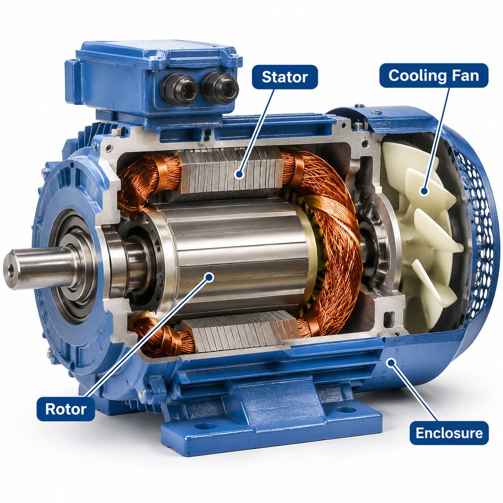
A brake motor (also called a motor with brake or electromagnetic brake motor) is a standard electric motor, most often a three-phase AC induction motor, fitted with a brake mounted on the non-drive end, usually under or behind the fan cover. The brake acts on the motor shaft, so it can bring the shaft to rest after the motor is switched off and then hold it stationary.
The key point is that most motor brakes are fail-safe: they are engaged by springs and released electrically. If the supply is switched off deliberately, an emergency stop is pressed, or the power fails, the brake applies on its own. That makes a brake motor a common choice wherever coasting to a stop, drifting under load, or back-driving would be unsafe or would spoil the process.
A typical example is the JWMotor YEJ series: a cast-iron, IEC-frame, three-phase induction motor with an integrated electromagnetic brake. Because the motor follows IEC mounting dimensions, it can be used on its own or as the drive motor on R/F/K/S series gear motors. If you are new to geared drives, see what is a gear motor for background.
How Do Electric Motor Brakes Work?
Most brake motors use a spring-applied, electromagnetically released disc brake. Its main parts are:
- Magnet body with coil: fixed to the motor end shield; it produces the magnetic field when energized.
- Armature plate: a steel plate that the coil can pull in against the springs.
- Compression springs: push the armature plate toward the brake disc.
- Brake disc (friction rotor): a disc with friction linings, keyed or splined to the motor shaft so it turns with it.
- Friction surface: the end shield or a separate flange the disc is pressed against.
When power is off, the springs push the armature plate against the brake disc, clamping it between the armature and the friction surface. Friction between the linings and these surfaces produces the braking torque that stops the shaft and holds it.
When the motor is started, the brake coil is energized at the same time. The magnetic field pulls the armature plate back across a small air gap (typically a few tenths of a millimetre), compressing the springs and freeing the disc, so the motor shaft turns without drag.
When the motor is stopped or power fails, the coil de-energizes, the magnetic field collapses, and the springs re-apply the brake. Stopping is not literally instantaneous: there is a short brake reaction time (tens to a few hundred milliseconds, depending on brake size and how the coil circuit is switched) followed by a braking period while the load decelerates.
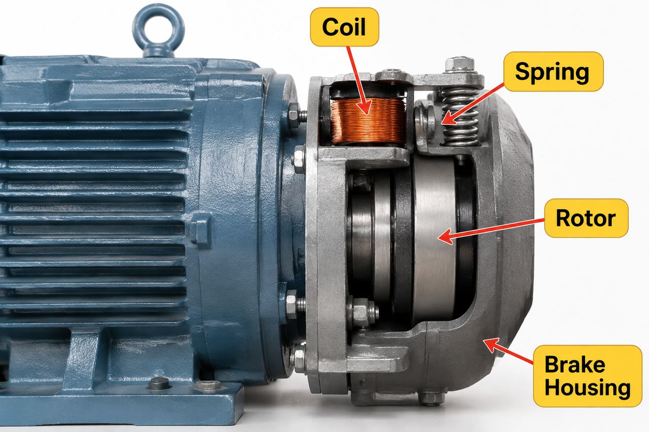
Electromagnetic brake on a cast-iron motor: coil, springs, brake disc (rotor) and housing.
AC supply, DC brake coil
Most brake coils run on DC. In a three-phase brake motor the DC is normally produced by a small rectifier in the terminal box, fed either from the motor terminals or from a separate AC supply. Common arrangements are:
- Half-wave or full-wave rectifier, AC-side switching: simple and inexpensive, but the brake reacts more slowly because the coil’s stored energy has to decay through the rectifier.
- DC-side switching (or a fast-acting rectifier): interrupting the DC circuit makes the brake apply much faster, which matters for hoists and accurate stopping.
- Separate brake supply: recommended when the motor is driven by a frequency inverter, because the inverter output is not a suitable supply for the rectifier.
Some designs use AC-powered brake magnets, but DC coils are the more common choice today because they are quieter and more tolerant of frequent switching.
Manual release and adjustment
Many brake motors offer a manual release lever so the load can be moved by hand during installation or after a power failure. As the friction linings wear, the air gap grows; some brakes allow it to be reset, others require the disc to be replaced. Regular checks of the air gap and lining thickness are part of normal maintenance.
Brake Motor vs Standard Motor
A brake motor and a standard motor of the same frame size use the same stator, rotor and bearings, so their running performance is essentially the same. The difference is what happens when the power is removed.
| Aspect | Standard motor | Brake motor |
|---|---|---|
| Stopping | Coasts to rest; time depends on load inertia and friction | Brake stops the shaft within a short, repeatable time |
| Holding the load | No holding torque at standstill | Holds the shaft when de-energized (fail-safe) |
| Behaviour on power failure | Load can drift, run on, or be back-driven | Brake applies automatically |
| Length | Standard | Longer, because of the brake on the non-drive end |
| Wiring | Motor supply only | Motor supply plus brake rectifier/coil supply |
| Maintenance | Bearings, cooling | Plus brake air gap and lining wear |
| Typical uses | Fans, pumps, compressors, continuously running machines | Hoists, conveyors, doors, machine tools, positioning drives |
A standard motor can be fitted with an external brake or stopped electrically (for example, DC injection or inverter braking), but electrical braking alone does not hold a load when power is lost. Where holding at standstill or a fail-safe stop is required, a mechanical brake is still needed, and an integrated brake motor is usually the most compact way to provide it.
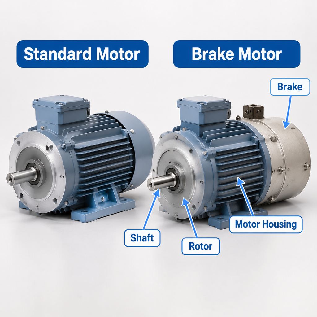
A standard motor (left) and a brake motor (right); the brake adds length at the non-drive end.
Common Applications of Brake Motors
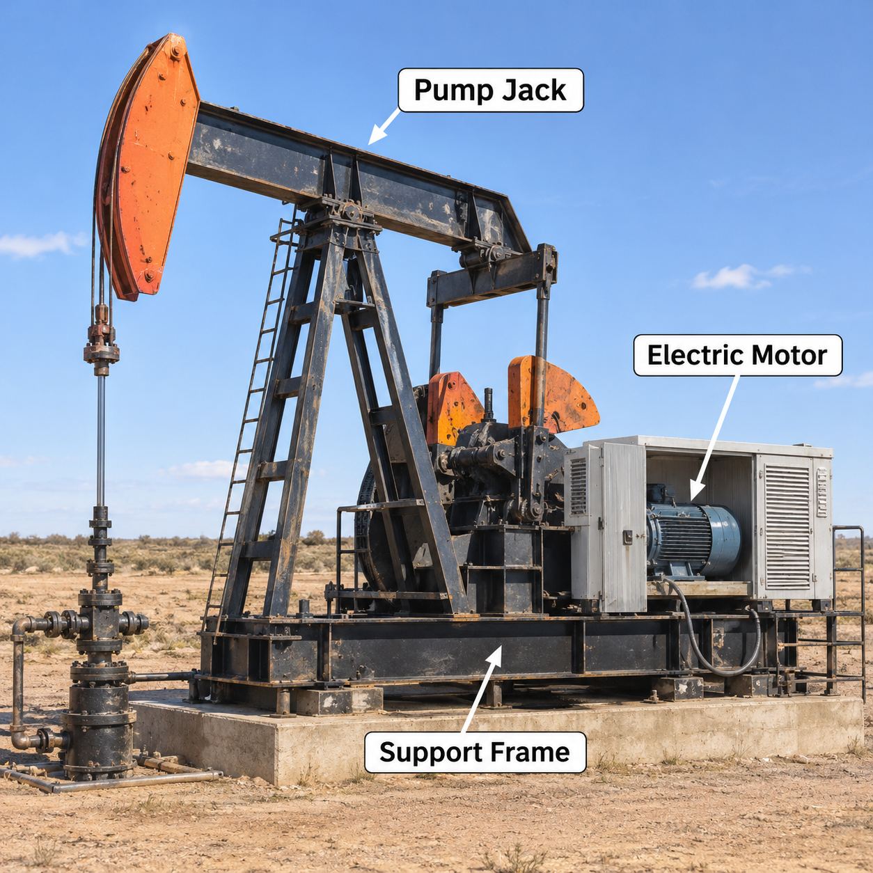
- Hoists and cranes: the brake holds a suspended load when the motor stops and prevents it from dropping if power fails. Lifting applications usually call for higher brake torque margins and fast brake response. See our material handling solutions.
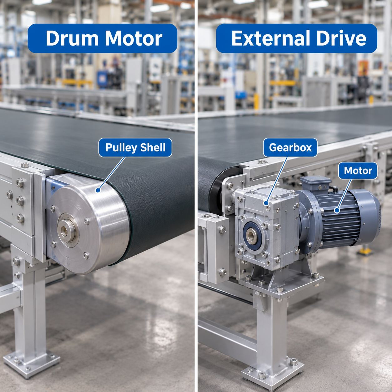
- Conveyors: brake motors stop belt and roller conveyors at a defined point and prevent inclined conveyors from running back under load, which is common in mining and aggregates, packaging and logistics.
- Doors, gates and shutters: the brake holds industrial doors, roller shutters and sliding gates in position and stops them at the end of travel.
- Machine tools: a brake shortens run-down time of spindles and feeds after switching off, improving safety and cycle time on saws, lathes, drilling and woodworking machines.
- Positioning and indexing: turntables, transfer cars, stackers and lifting tables use brake motors for repeatable stopping. For very high positioning accuracy, a brake motor is usually combined with an inverter and a position sensor or encoder.
How to Select a Brake Motor
- Determine the brake torque. The brake must stop the load within the required time or distance and then hold it. Base the calculation on the load torque, the total inertia (motor, gearbox and load), the required stopping time and the duty. As a starting point, brake torque is usually chosen to be at least equal to the motor’s rated torque, and often around 1.5 to 2 times rated torque for lifting applications. Your application’s safety standards and the brake manufacturer’s data take precedence over rules of thumb.
- Choose the brake voltage and rectifier. Confirm the coil voltage (for example, DC 99 V or 198 V from a rectifier on a 220 V or 400 V supply, or 24 V DC from a control supply) and whether AC-side or DC-side switching is needed for the reaction time you require. Specify a separate brake supply for inverter-driven motors.
- Check switching frequency and wear. Frequent starts and stops, or braking high inertia, generate heat and wear in the brake. Check permissible switching work per operation and per hour, and plan inspection intervals for the air gap.
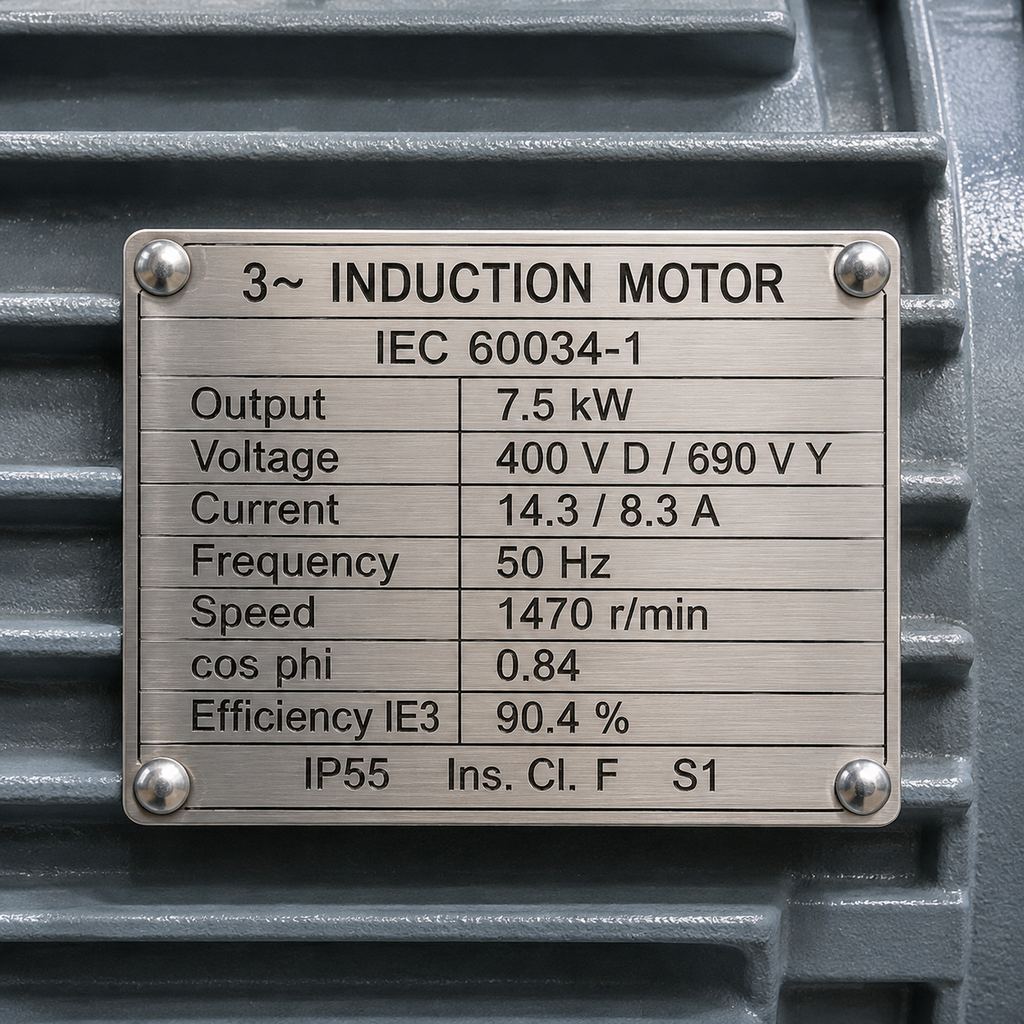
- Match the IP rating to the environment. IP55 is common for indoor industrial use; dusty, wet or outdoor locations may need IP56 or higher, plus attention to brake seals and condensation.
- Select the efficiency class. Brake motors are available in IEC efficiency classes such as IE2, IE3 and higher. Local regulations often set a minimum class, and higher-efficiency motors reduce energy cost on drives that run for long periods.
- Confirm the mechanical interface. Check the IEC frame size, mounting (foot, flange or both), shaft dimensions and overall length including the brake. If the motor will drive a gearbox, confirm the motor flange and shaft match the reducer; YEJ motors can be supplied as the input motor on R, F, K and S series gear units.
- Specify options. Manual release lever, brake release monitoring, anti-condensation heaters, thermal protection or a forced-ventilation fan for low-speed inverter operation can be specified as needed. For non-standard requirements, see customization.
Brake motors are listed in our special-purpose motors category, and the full range is in all products.
Frequently Asked Questions About Brake Motors
What is a motor brake?
A motor brake is a device mounted on an electric motor that stops and holds the motor shaft. In industrial motors it is usually a spring-applied friction brake that is released electromagnetically while the motor runs and applies automatically when power is removed.
How do electric motor brakes work?
Springs press a friction disc that is attached to the motor shaft against a fixed surface. When the brake coil is energized, its magnetic field pulls the armature plate back and releases the disc. Removing power lets the springs apply the brake again.
What is the difference between an AC brake and a DC brake on a brake motor?
The motor itself is normally a three-phase AC motor in both cases; the terms refer to the brake coil. A DC brake coil is fed through a rectifier and is the more common type, offering quiet operation and good tolerance of frequent switching. An AC brake magnet is fed directly from the AC supply and can react quickly but is generally noisier. Reaction time on DC brakes depends heavily on whether the circuit is switched on the AC or DC side.
Can a brake motor be used with a frequency inverter?
Yes. The inverter controls speed and deceleration, and the brake holds the load at standstill and provides a fail-safe stop. The brake coil should have its own supply rather than being fed from the inverter output, and the inverter should be set to release the brake only once motor torque is established.
Can brake motors be combined with gear motors?
Yes. A brake motor can be mounted as the input motor on helical, parallel-shaft, helical-bevel or worm gear units such as R, F, K and S series. The gearbox multiplies the brake’s holding torque at the output shaft by approximately the gear ratio, which is why geared brake motors are widely used on conveyors and lifting equipment.
How often does a motor brake need maintenance?
It depends on switching frequency and the energy absorbed per stop. Check the air gap and lining wear periodically, and more often on hoists and high-cycle applications. Replace the brake disc when the lining reaches its minimum thickness or the air gap can no longer be adjusted.