A torque speed curve shows how much torque a motor produces at every speed from standstill up to synchronous speed. For a three-phase induction motor, the curve tells you five things a nameplate does not. It shows the torque at start (locked-rotor torque), the weakest point while accelerating (pull-up torque), and the peak the motor can reach before it stalls (breakdown torque). It also shows where the motor runs at full load (the rated point) and the speed it can never quite reach (synchronous speed). Lay the load’s torque curve over the motor’s and you can see whether the motor will start the machine, accelerate it, and run it without overheating. Rated kW alone cannot tell you that.
What a Torque Speed Curve Shows
The horizontal axis is shaft speed, often given as a percentage of synchronous speed. The vertical axis is torque, usually in N·m or as a percentage of rated (full-load) torque. A line-started induction motor has a characteristic shape. It starts at a fairly high torque, dips slightly, rises to a peak, and then drops steeply to zero torque at synchronous speed.
Synchronous speed is the speed of the rotating magnetic field in the stator:
n_s (rpm) = 120 × f / p, where f is the supply frequency in Hz and p is the number of poles.
| Poles | 50 Hz Synchronous Speed (rpm) | 60 Hz Synchronous Speed (rpm) |
|---|---|---|
| 2 | 3000 | 3600 |
| 4 | 1500 | 1800 |
| 6 | 1000 | 1200 |
| 8 | 750 | 900 |
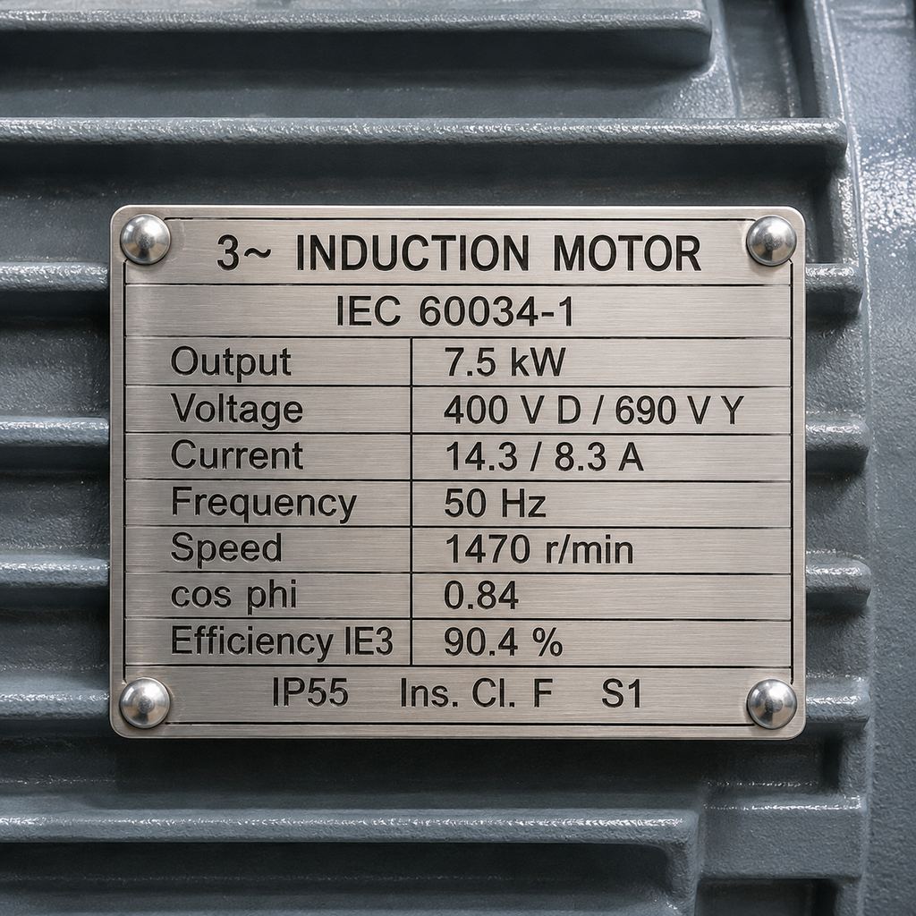
Slip is the gap between synchronous speed and actual shaft speed: s = (n_s − n) / n_s. An induction motor needs some slip to produce torque. If the rotor turned at synchronous speed, no current would be induced in it and the torque would be zero. For example, a 4-pole, 50 Hz motor with a nameplate speed of 1,470 rpm runs at (1500 − 1470) / 1500 = 2% slip. As the load rises, the operating point slides down the steep right-hand side of the curve: speed falls slightly and torque rises to match the load.
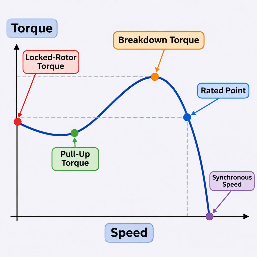
The Five Points to Read on the Curve
The US Department of Energy’s Premium Efficiency Motor Selection and Application Guide defines the three starting-related torques as follows. Locked-rotor torque is “the minimum torque produced by the motor at rated voltage and frequency at all angular positions of the rotor”. Pull-up torque is “the minimum torque developed by the motor during acceleration”. Breakdown torque is “the maximum torque that the motor can supply before stalling.”
- Locked-rotor torque (LRT): torque at zero speed. It must exceed the load’s breakaway torque, or the shaft will not turn.
- Pull-up torque: the lowest point of the curve between standstill and the breakdown peak. A motor can start a load and still stall here if the load torque is higher than this dip.
- Breakdown torque: the peak of the curve. It is the motor’s short-term overload limit. If the load exceeds it, the motor drops off the curve and stalls. It is not a continuous rating, because the motor would overheat.
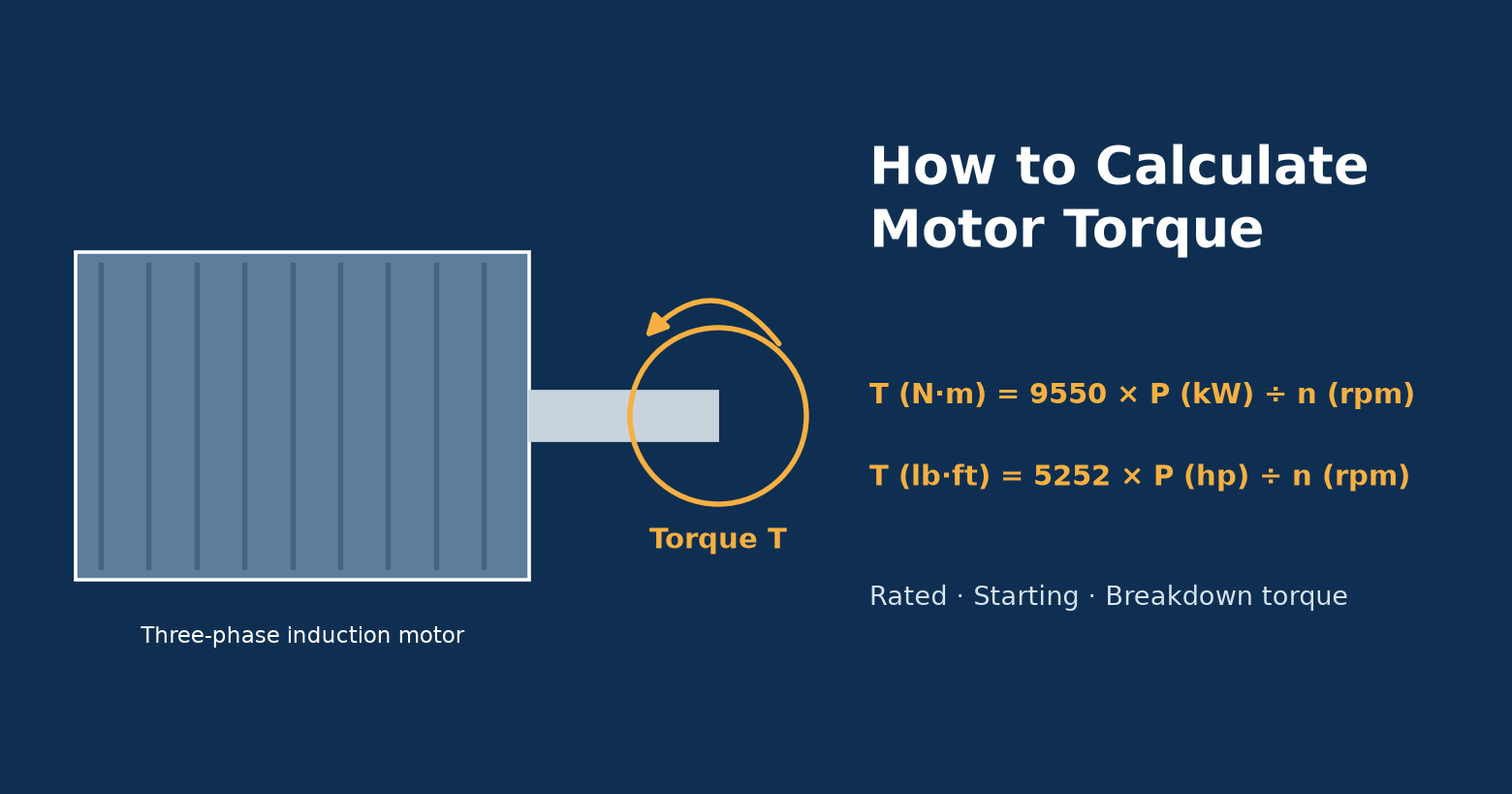
- Rated point: rated torque at nameplate speed, on the steep stable part of the curve just below synchronous speed. Rated torque in N·m is 9550 × P (kW) / n (rpm). See how to calculate motor torque for worked examples.
- Synchronous speed: the point where the curve reaches zero torque. A loaded induction motor always runs below it.
The area between the motor curve and the load curve is the accelerating torque. The larger it is, the faster the load reaches speed. Where the gap is small, acceleration is slow and the motor heats up more during the start.
NEMA Design A, B, C and D Curves
NEMA MG 1 groups general-purpose cage induction motors by the shape of their torque speed curve. The standard sets minimum locked-rotor, pull-up and breakdown torques for each design as a percentage of full-load torque. The minimums depend on horsepower and synchronous speed.
- Design B is the general-purpose design and the most common. It suits centrifugal fans, pumps and similar loads where starting torque requirements are moderate.
- Design A has the same torque minimums as Design B, but its starting current is not limited. The DOE guide notes that Design A motors “have higher starting current and start-up torque characteristics”.
- Design C has higher locked-rotor and pull-up torque. It is meant for loads that start under load, such as loaded conveyors, crushers and reciprocating compressors.
- Design D has very high locked-rotor torque, high slip and no distinct breakdown peak. It is used for high-inertia, peak-load machines such as punch presses and hoists. NEMA requires at least 275% locked-rotor torque for 4-, 6- and 8-pole Design D motors of 150 hp and below. Design D is a special design; JW’s standard three-phase lines are general-purpose motors, not Design D.
Minimum values from NEMA MG 1 Part 12 (Tables 12-2 and 12-3 and clauses 12.39–12.40) for 4-pole motors (1800 rpm at 60 Hz, 1500 rpm at 50 Hz):
| Rating | Design | Min. Locked-Rotor Torque | Min. Pull-Up Torque | Min. Breakdown Torque |
|---|---|---|---|---|
| 5 hp (3.7 kW) | A / B | 185% | 130% | 225% |
| 10 hp (7.5 kW) | A / B | 165% | 115% | 200% |
| 50 hp (37 kW) | A / B | 140% | 100% | 200% |
| 100 hp (75 kW) | A / B | 125% | 100% | 200% |
| 5 hp (3.7 kW) | C | 255% | 180% | 200% |
| 10 hp (7.5 kW) | C | 250% | 175% | 200% |
| 50 hp (37 kW) | C | 200% | 150% | 190% |
| 100 hp (75 kW) | C | 200% | 140% | 190% |
These are minimums at rated voltage and frequency. Real motors often exceed them, so always ask the supplier for the actual curve. The DOE guide summarizes the typical ranges for medium motors as follows:
- Design B: locked-rotor torque 70–275%, breakdown torque 175–300%, starting current 600–700% of rated current.
- Design C: locked-rotor torque 200–250%, breakdown torque 190–225%.
IEC Design N and Design H
IEC motors are classified by starting performance under IEC 60034-12. The standard “specifies the parameters for eight designs of starting performance of single-speed three-phase 50 Hz or 60 Hz cage induction motors”. The two basic designs are:
- Design N (normal starting torque): 2-, 4-, 6- or 8-pole motors from 0.12 kW to 1,600 kW, intended for direct-on-line starting. Besides minimum locked-rotor, pull-up and breakdown torques, the motor’s torque at any speed up to the breakdown point must be at least 1.3 times a curve that rises with the square of speed and equals rated torque at rated speed. The standard notes that the 1.3 factor allows for a 10% undervoltage at the terminals during acceleration. Its starting test also assumes a load torque proportional to the square of speed. That makes design N a natural fit for fans and centrifugal pumps.
- Design H (high starting torque): 4-, 6- or 8-pole motors from 0.12 kW to 160 kW at 60 Hz. Its starting test assumes a constant load torque equal to rated torque, independent of speed. That is the profile of a loaded conveyor.
Variants with an E (NE, HE) allow higher locked-rotor current for IE3 and higher-efficiency motors. Variants with a Y (NY, HY) are for star-delta starting; in star connection their minimum locked-rotor and pull-up torques are only 25% of the design N or H values. NEMA and IEC designs overlap in purpose: B/N are both “normal”, C/H both “high starting torque”. But the two systems are not one-to-one equivalents, so compare actual curves when you replace a motor across standards.
Matching the Motor Curve to the Load Curve
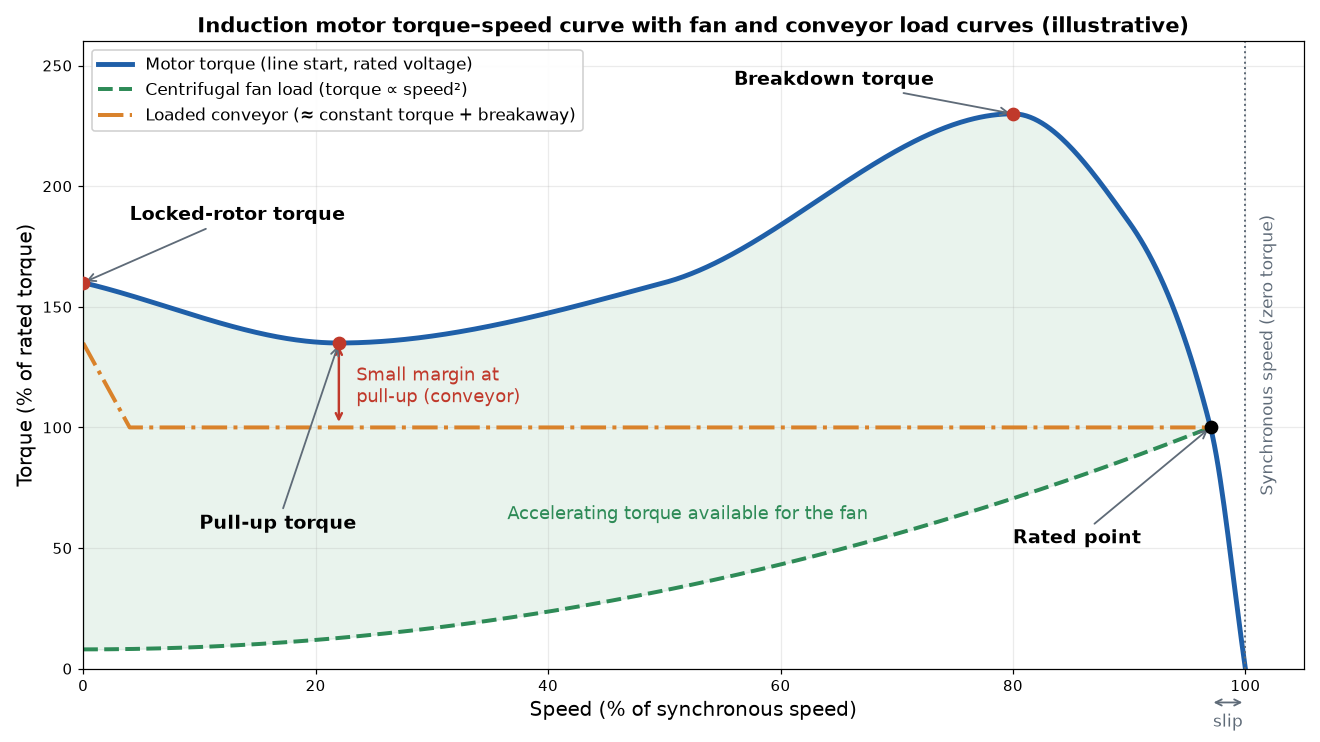
The motor accelerates as long as its torque is above the load torque at every speed. It settles where the two curves cross. Two load types cover most industrial drives:
- Square-law loads (centrifugal fans and pumps): torque rises roughly with the square of speed, so power rises with the cube. Starting torque demand is low; the main check is that the motor can carry the load at full speed. ABB’s Technical Guide No. 7 calls this “the most common load type”.
- Constant-torque loads (conveyors, screw compressors, feeders): torque stays roughly the same at every speed, and loaded conveyors add extra breakaway torque at standstill. Here the pull-up torque is often the critical point. In the chart above the motor clears the conveyor line at pull-up, but only just.
Supply voltage matters as much as the catalog curve. Induction motor torque falls roughly with the square of the voltage, so a 10% voltage drop during starting cuts available torque by about 19%. That is why IEC design N builds in the 1.3 factor. Long cables, weak transformers and star-delta starting all reduce the torque the load actually sees.
How a VFD Changes the Torque Speed Curve
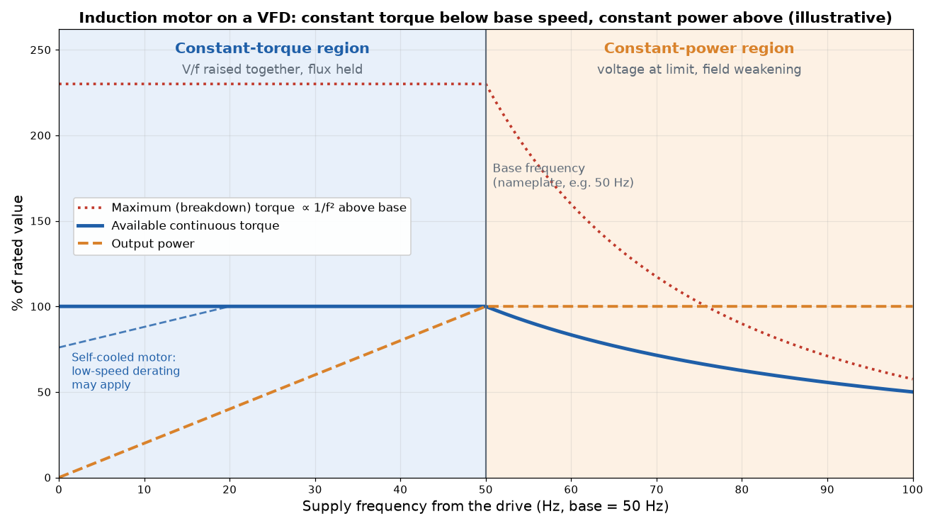
A variable frequency drive does not move the motor along its line-start curve. It shifts the whole curve: each frequency produces a new curve with a lower synchronous speed. Two operating regions result:
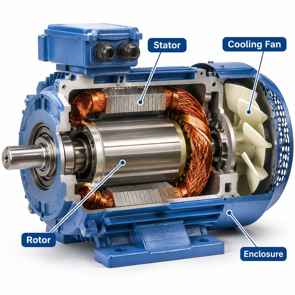
- Constant-torque region (below base frequency): the drive raises voltage and frequency together to keep the magnetic flux constant, so rated torque is available across the speed range. Power rises in proportion to speed. Self-cooled motors may need derating at low speed because the shaft-mounted fan moves less air.
- Constant-power region (above base frequency): the drive cannot raise the voltage further, so the flux weakens. ABB’s guide explains that “in the field weakening range the motor can operate on constant power which is why the field weakening range is sometimes also called the constant power range.” Available torque falls roughly in proportion to 1/f. Breakdown torque falls faster, roughly with 1/f², so the overload margin shrinks as speed rises.
The drive also limits current, and ABB notes that frequency converters typically limit maximum torque to 70% of the motor’s breakdown torque. A VFD start draws far less current than a direct-on-line start, and it can deliver near-rated torque from low speed. For conveyors and other constant-torque loads, that often solves a starting problem without moving to a high-torque design.
JW’s variable frequency motors (YVF2 series) are built for this duty. They hold constant torque from 5 Hz to 50 Hz and constant power above 50 Hz, up to 100 Hz on most models. An independent cooling fan keeps them cool at low speed.
Worked Example: Starting a Loaded Conveyor
Take a 4-pole, 50 Hz motor rated 7.5 kW (about 10 hp) at 1,470 rpm driving a belt conveyor that needs full rated torque at every speed. Assume the motor just meets the NEMA Design B minimums; a real motor’s curve is usually higher.
- Rated torque: 9550 × 7.5 / 1470 = 48.7 N·m. Slip is (1500 − 1470) / 1500 = 2%.
- Design B minimums (10 hp, 1500 rpm): locked-rotor torque 165% = 80.4 N·m, pull-up torque 115% = 56.0 N·m, breakdown torque 200% = 97.4 N·m.
- Check pull-up against the load: 56.0 N·m is above the 48.7 N·m conveyor load at full voltage, but the margin is only 7.3 N·m. With a 10% voltage dip during starting, pull-up torque falls to about 0.81 × 56.0 = 45.4 N·m. That is below the load, so the conveyor could hang at low speed and the motor would overheat.
- Options: use a Design C or design H motor (Design C minimum pull-up at 10 hp is 175% = 85.2 N·m, or about 69.0 N·m at 90% voltage). Alternatively, start the conveyor with a VFD, or confirm with the supplier that the actual motor curve sits well above the minimums.
- Running above base speed on a VFD: at 75 Hz the motor runs at about 2,205 rpm. At constant power, available torque is 9550 × 7.5 / 2205 = 32.5 N·m. Breakdown torque falls to about (50/75)² = 44% of its 50 Hz value: 0.44 × 97.4 ≈ 43 N·m, leaving roughly 33% overload margin. A constant-torque conveyor needing 48.7 N·m therefore cannot run at 75 Hz on this motor. A fan would also need checking, because its torque rises with speed.
What to Ask a Motor Supplier For
- The torque speed curve at your voltage, frequency and starting method (direct-on-line, star-delta, soft starter or VFD), not a generic catalog plot.
- Locked-rotor, pull-up and breakdown torque values in N·m or % of rated torque, plus locked-rotor current.
- The design category (NEMA B/C or IEC N/H) and the maximum load inertia the motor can start.
- For VFD duty: the continuous torque at your lowest and highest frequencies, and whether forced ventilation is needed.
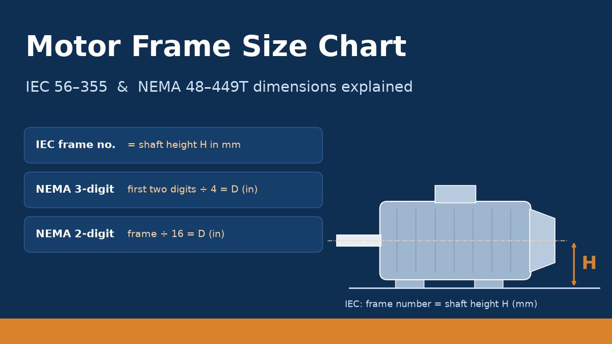
- Frame and mounting data for the replacement. The motor frame size chart explains IEC and NEMA frame dimensions.
JW’s YE3 series motors are IE3 three-phase asynchronous motors in IEC frames 80–400 (0.75–630 kW, 2–10 poles). They can also run on a frequency converter. Send us your load type, starting method and supply data, and we will check the torque speed curve against your machine before you order.
FAQ
What is a torque speed curve?
It is a graph of a motor’s output torque against shaft speed at a given voltage and frequency. For an induction motor, it shows locked-rotor torque at zero speed, the pull-up minimum, the breakdown peak, the rated operating point and zero torque at synchronous speed.
Why does an induction motor never reach synchronous speed?
Torque comes from current induced in the rotor, and that needs relative motion between the rotor and the rotating field. At synchronous speed there is no relative motion, no rotor current and no torque. So a loaded motor always runs slightly slower, usually by a few percent of slip.
What is the difference between starting torque and breakdown torque?
Starting (locked-rotor) torque is the torque at standstill and decides whether the motor can break the load away. Breakdown torque is the maximum torque on the curve, reached near full speed, and sets the short-term overload limit. On most general-purpose motors breakdown torque is higher than locked-rotor torque. NEMA Design D is the exception: its peak is at or near standstill.
Why can a motor start but fail to reach full speed?
Its torque may dip below the load torque at pull-up, the low point of the curve during acceleration. Low supply voltage during starting makes this worse because torque falls roughly with the square of voltage. Check pull-up torque against the load curve, not just locked-rotor torque.
What do NEMA Design B and Design C mean?
They are NEMA MG 1 torque-speed classes. Design B is the general-purpose class with normal starting torque and limited starting current. Design C has higher locked-rotor and pull-up torque for loads that start under load, such as loaded conveyors and crushers.
What are IEC design N and design H?
They are IEC 60034-12 starting classes for cage induction motors. Design N gives normal starting torque and is tested against a load whose torque rises with the square of speed (fans, pumps). Design H gives high starting torque and is tested against a constant load equal to rated torque (conveyors).
Does a VFD change the motor’s torque speed curve?
Yes. Below base frequency the drive keeps flux constant, so rated torque is available at reduced speed (constant-torque region). Above base frequency the voltage is at its limit, flux weakens, and the motor delivers roughly constant power with falling torque. Breakdown torque drops roughly with 1/f² in that region.
How do I read the rated point on the curve?
Find rated torque (9550 × kW ÷ rpm) on the vertical axis and nameplate speed on the horizontal axis. The rated point sits on the steep right-hand side of the curve, just below synchronous speed. The motor should run on this stable side at all normal loads.