A gear motor is a single unit that combines an electric motor with a gearbox, also called a speed reducer. The motor provides rotation at its rated speed, and the gearbox converts that rotation into a lower output speed with higher torque. People also call these units gearmotors, geared motors, or gearbox motors. This article covers AC gear motors used in industrial equipment: how they are built, how gear ratio affects output torque, the four common gearbox types, the main advantages, and where they are typically used.
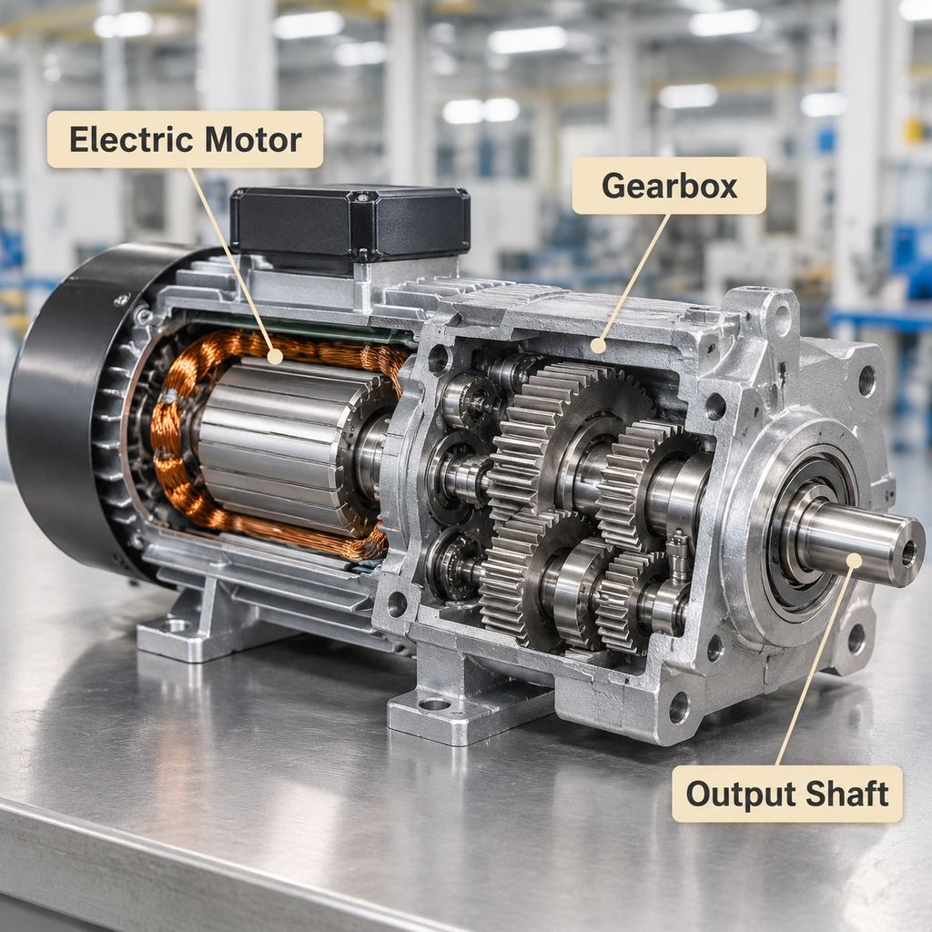
Cutaway view of a gear motor: electric motor, gearbox, and output shaft.
What Is a Gear Motor? Structure of an AC Gear Motor
An AC gear motor has two main sections that are joined into one housing or flanged together:
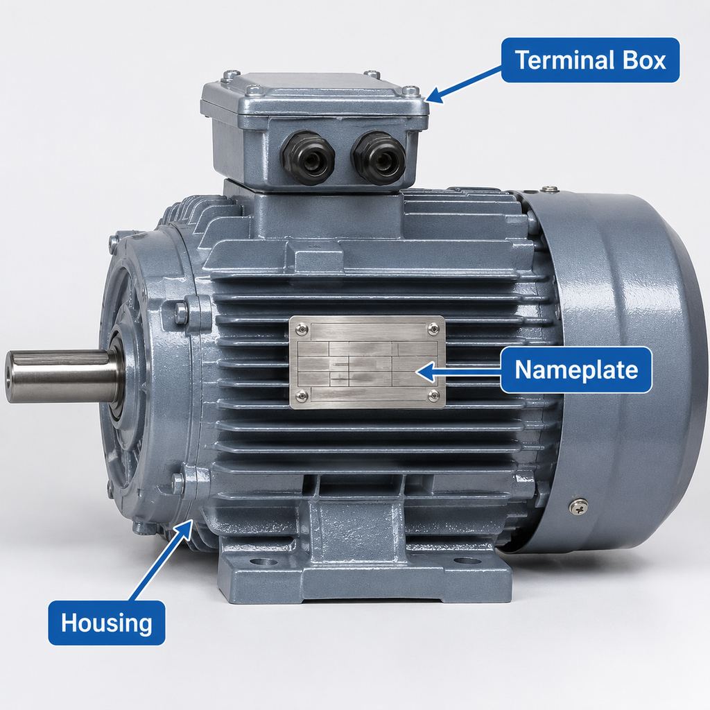
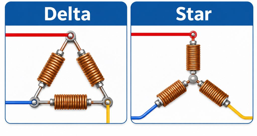
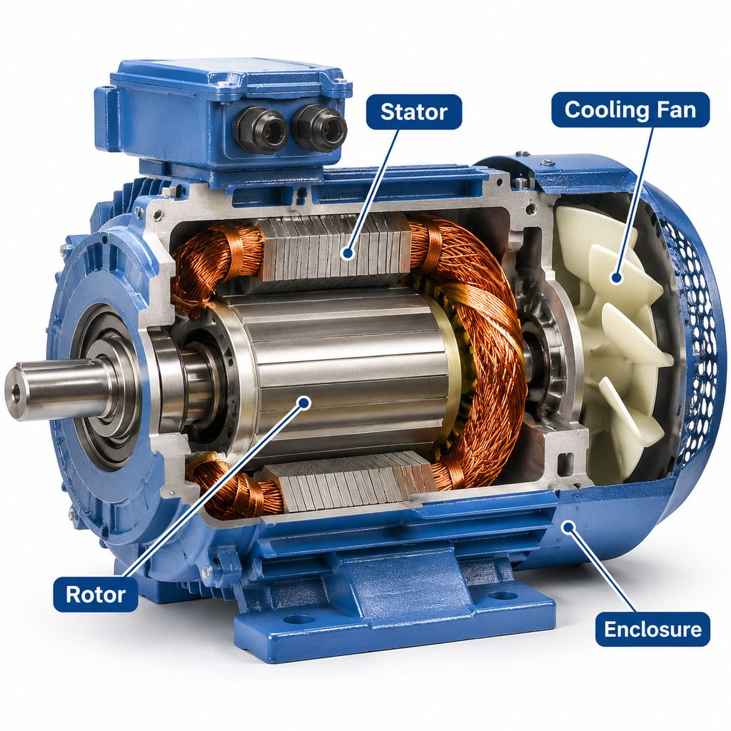
- Electric motor. In industrial AC gearmotors this is usually a three-phase induction motor. It turns at a speed set by the supply frequency and the number of poles; on a 60 Hz supply, a 4-pole motor runs at roughly 1,750 rpm under load (about 1,450 rpm on 50 Hz).
- Gearbox. One or more gear stages mounted on shafts and bearings inside a sealed, lubricated housing. The motor shaft drives the input gear (pinion), and each stage reduces speed further.
- Output shaft or hollow shaft. The gearbox output connects to the driven machine, either through a solid shaft with a key or a hollow shaft that slides onto the machine shaft.
- Housing, seals, and mounting features. Foot mounts, flanges, or torque arms locate the unit, while oil seals keep lubricant in and contamination out.
Because the motor and gearbox are designed to fit each other, there is no separate coupling to align, and the assembly takes less space than a motor and reducer installed side by side.
Gear Ratio and Output Torque
The gear ratio is the ratio of input speed to output speed. In a single gear pair it equals the number of teeth on the driven gear divided by the number of teeth on the driving gear. Multi-stage gearboxes multiply the ratios of each stage.
Two simple relationships describe what the gearbox does:
- Output speed = motor speed ÷ gear ratio. A motor running at 1,750 rpm through a 25:1 ratio gives about 70 rpm at the output.
- Output torque ≈ motor torque × gear ratio × gearbox efficiency. Power is conserved apart from losses, so when speed drops, torque rises by about the same factor.
In practice, selection starts from the load: the torque and speed the machine needs, how many hours a day it runs, and how many starts and stops it sees. These factors set the required ratio, the motor power, and a service factor that keeps the gearbox within its rated limits. Manufacturer catalogs list output speed, output torque, and permitted overhung load for each ratio, and those values should be checked rather than calculated from rules of thumb alone.
Types of Gear Motors: R, F, K, and S
Industrial gear motors are commonly grouped by gearbox design. Many catalogs use the R, F, K, and S series names for these four types.
| Type | Gearing | Shaft arrangement | Typical traits |
|---|---|---|---|
| R series | Helical | Inline (coaxial) | Compact, efficient, wide ratio range |
| F series | Parallel shaft helical | Parallel offset, often hollow shaft | Slim, shaft-mounted on driven shaft |
| K series | Helical-bevel | Right angle | High efficiency for a right-angle drive, high torque |
| S series | Helical-worm | Right angle | Compact, lower cost, lower efficiency |
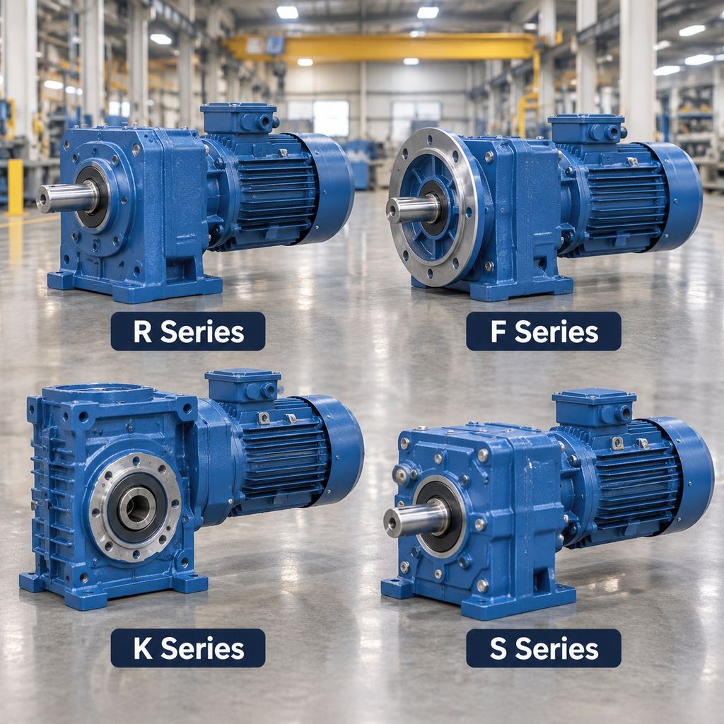
The four common gearbox types: R, F, K, and S series.
R series: helical inline gear motor
The output shaft is on the same axis as the motor shaft. Helical gears have angled teeth that engage gradually, which gives smooth, relatively quiet running and good efficiency per stage. Inline units suit general drives such as conveyors, mixers, and pumps where there is room along the axis of the drive.
F series: parallel shaft gear motor
The output shaft is parallel to, but offset from, the motor shaft. Units are often supplied with a hollow output shaft and a torque arm so they can mount directly on the driven shaft. The flat, narrow shape is useful along conveyor lines and in other places where the drive must sit close to the machine frame.
K series: helical-bevel gear motor
A bevel gear stage turns the drive through 90 degrees, followed by helical stages. Helical-bevel gearing keeps efficiency high for a right-angle unit and handles high torque, which is why K-type units are common on heavier conveyors, hoisting drives, and other continuous-duty equipment.
S series: helical-worm gear motor
A helical input stage is followed by a worm and worm wheel, giving a right-angle output in a compact housing. Worm gearing slides rather than rolls, so efficiency is lower than helical or bevel designs, especially at high ratios, and more of the input power becomes heat. In return, S-type units are compact and usually lower in cost. Some high-ratio worm gears resist back-driving, but this should not be relied on as a brake; use a brake motor where the load must be held.
How to Choose an AC Gear Motor
- Define torque and speed at the output. Work out the torque needed to move the load, including start-up, and the output speed the process requires. This sets the gear ratio and motor size.
- Describe the duty. Note running hours per day, starts per hour, and whether the load is uniform, moderately shocking, or heavily shocking. These determine the service factor.
- Choose the shaft arrangement. Use an R (inline) or F (parallel shaft) unit when the drive can sit in line with or beside the driven shaft; use a K or S unit when a right-angle output saves space.
- Weigh efficiency against cost. For drives that run many hours, the higher efficiency of helical and helical-bevel gearing reduces energy use and heat. For intermittent, low-power duty, a helical-worm unit may be adequate. The motor’s own efficiency class (for example IE2, IE3, or IE4) is a separate choice from the gearbox type.
- Check the environment. Consider dust, washdown, humidity, ambient temperature, and chemicals when choosing enclosure rating (for example IP55 or higher), paint system, and seals.
- Confirm mounting and connection. Check foot, flange, or shaft mounting; solid or hollow output shaft; mounting position (which affects lubricant quantity); and permitted overhung or axial loads.
- Plan for variable speed and maintenance. If speed must change during operation, a variable frequency drive can be used with a suitable motor. Check lubricant type, change intervals, and spare part availability.
For an overview of these four gearbox types, see the R/F/K/S series gear motor page and the gear motors category. Where a standard unit does not fit, ratio, shaft, flange, or mounting changes are described on the customization page.
What Are the Main Advantages of Gear Motors?
- High torque at low speed. The gearbox lets a small, standard-speed motor drive loads that need slow, strong rotation.
- Compact, integrated design. One unit replaces a motor, coupling, base, and separate reducer, saving space and reducing alignment work.
- Simpler installation. Factory-matched components arrive as an assembly, which shortens commissioning.
- Wide choice of ratios and arrangements. Inline, parallel shaft, and right-angle versions with many ratios cover most industrial speed requirements.
- Reduced load on the motor. The gear reduction lowers the load inertia seen by the motor, which helps when starting and controlling heavy loads.
- Good efficiency with helical gearing. Helical and helical-bevel types lose relatively little power per stage, which matters on drives that run continuously.
- Compatibility with AC drives. Pairing an AC gear motor with a variable frequency drive adds speed adjustment without changing gears.
Applications of AC Gearmotors
Conveyors and material handling
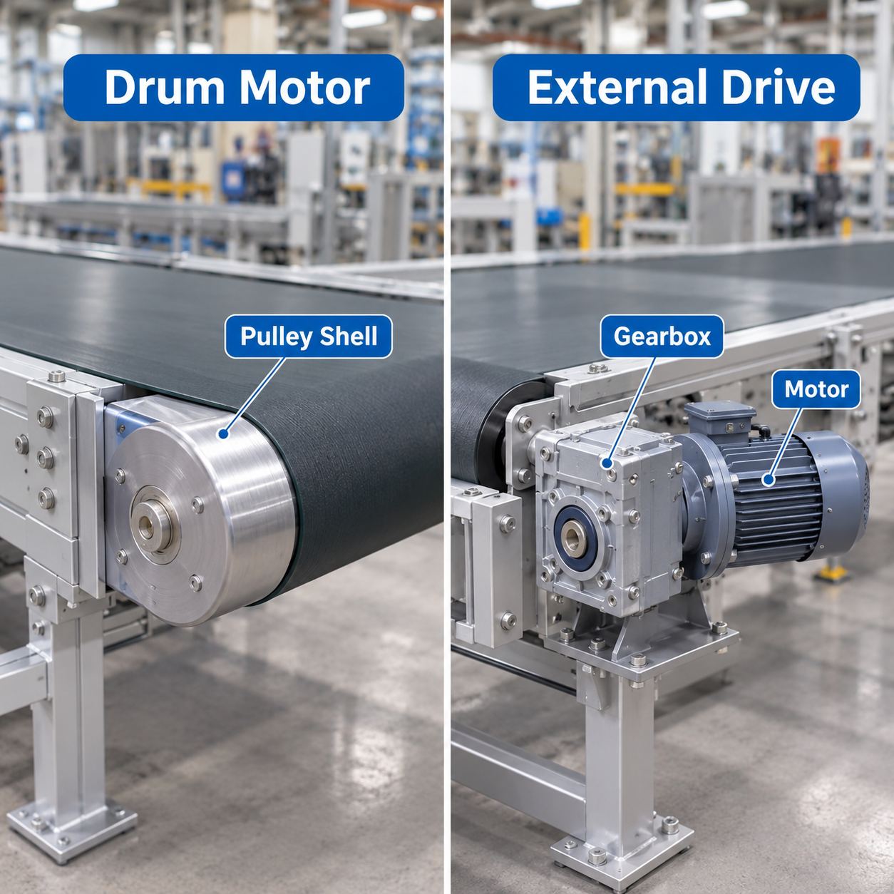
Belt, roller, chain, and screw conveyors need steady, low-speed torque, which is the main job of a gear motor. Parallel shaft units mount directly on conveyor head shafts, while right-angle units fit along the side of the frame. Other material handling uses include bucket elevators, palletizers, and sorting equipment. More on these uses is on the material handling page.
Mixing and agitation
Mixers, agitators, and kneaders run at low speed with high torque, often continuously. Inline helical and helical-bevel units are common here because of their efficiency and their ability to carry the loads from the mixing shaft.
Packaging and food and beverage processing
Packaging machines, bottling and filling lines, and indexing conveyors use gear motors for repeatable motion, often with a variable frequency drive for speed control. Food and beverage plants also need enclosures and finishes that withstand washdown. Related applications are described on the food and beverage page.
Frequently Asked Questions
What is the difference between a gear motor and a gearbox?
A gearbox is only the gear reducer; it needs a separate motor and coupling. A gear motor combines the motor and gearbox into one matched unit.
What is a gearbox motor?
“Gearbox motor” is another name for a gear motor: an electric motor with an attached gearbox that lowers output speed and raises output torque.
How does a gear motor increase torque?
By reducing speed. Apart from gearbox losses, output power equals input power, so a 20:1 reduction gives roughly 20 times the motor torque at one-twentieth of the speed, less the efficiency loss.
Can a gear motor be customized?
Often, yes. Common options include specific ratios, shaft types, flanges, mounting positions, enclosure ratings, and brakes. A full range of motor types is listed on the all products page.


2 thoughts on “What Is a Gear Motor?”